
Automatic Belt Feeder for the Shredder
Started 2y. Edited 1yStarted about 2 years ago. Last edit about 1 year ago
Machines
Completed
shredder
More Information


%20--%3e%3csvg%20version='1.1'%20id='Layer_1'%20xmlns='http://www.w3.org/2000/svg'%20xmlns:xlink='http://www.w3.org/1999/xlink'%20x='0px'%20y='0px'%20viewBox='0%200%2064%2063'%20style='enable-background:new%200%200%2064%2063;'%20xml:space='preserve'%3e%3cstyle%20type='text/css'%3e%20.st0{fill:%23231F20;}%20%3c/style%3e%3cdesc%3eCreated%20with%20Sketch.%3c/desc%3e%3cg%20id='Page-1'%3e%3cg%20id='OA-Logo-Black-Background'%3e%3cpath%20id='Shape'%20class='st0'%20d='M14.1,30.1c-1.5-0.8-8.6-3.8-14.1-7.8c1.8-3.4,3.1-5.6,5-9.1c2.7,1.1,1.9,0.5,4.6,1.7%20c0.8,0.4,10.1,4.5,13.8,6.2c2.4,1.1,4.7,2.2,7,3.3L43,30.5l8.1,3.9c4,2,7.2,3.5,11.3,5.5c0.5,0.3-3.7,9.4-3.7,9.4%20c-1.7-0.6-3.9-1.8-5.5-2.5c-4.7-2.1-9-3.9-13.7-6c-4-1.8-6.7-2.9-10.8-4.5C25,34.9,17.1,31.6,14.1,30.1z'/%3e%3cpath%20id='Shape_1_'%20class='st0'%20d='M12.1,54.9c-0.8,0.6-1.6,1.2-2.5,1.6c-0.4-0.5-0.9-1-1.3-1.5c-0.3-1.2-2.3-4.9-2.7-6.2%20c-0.1-0.4-0.7-2.2-0.8-2.6c0,0,5-3.4,8.2-5.9c3.2-2.6,6.2-5,9.3-7.5c1.4-1.1,3.9-2.5,5.3-3.5c2.5-1.7,13-9.1,15.6-10.5%20c5.4-3.3,11.1-6.3,16.8-9c1.7,3.5,1.8,3,3.8,6.9c0,0-17.8,13.5-22.7,17.1c-3.8,2.8-7.5,5.7-11.3,8.5c-1.7,1.3-3.5,2.4-5.2,3.7'/%3e%3cpath%20id='Shape_2_'%20class='st0'%20d='M20.8,2.9l-0.2-0.8C25,0,31.2-0.3,31.4,0.2c0.4,1.1,0.9,2.2,1.2,3.4c1.4,4.4,2.7,8.7,4,13.1%20c0.4,1.4,2.8,10,2.9,10.5c0.5,2.8,1.2,5.6,1.6,8.4c0.8,4.7,1.4,8.6,2.3,13.3c0.6,3.1,1.3,6.3,2.3,11.3c0,0-5.8,1.4-7.5,1.8%20c-0.8,0.2-1.5,0.4-2.4,0.6c-0.3-1.1-0.2-1.2-0.5-2.1c-0.9-3.7-1.8-7.3-2.6-11c-1.5-6.4-3-12.9-4.4-19.3%20c-1.2-5.4-2.6-10.7-4.4-15.9c-1-3.1-1.8-6.3-2.7-9.5C21.1,3.8,21,3.8,20.8,2.9z'/%3e%3c/g%3e%3c/g%3e%3c/svg%3e)


1
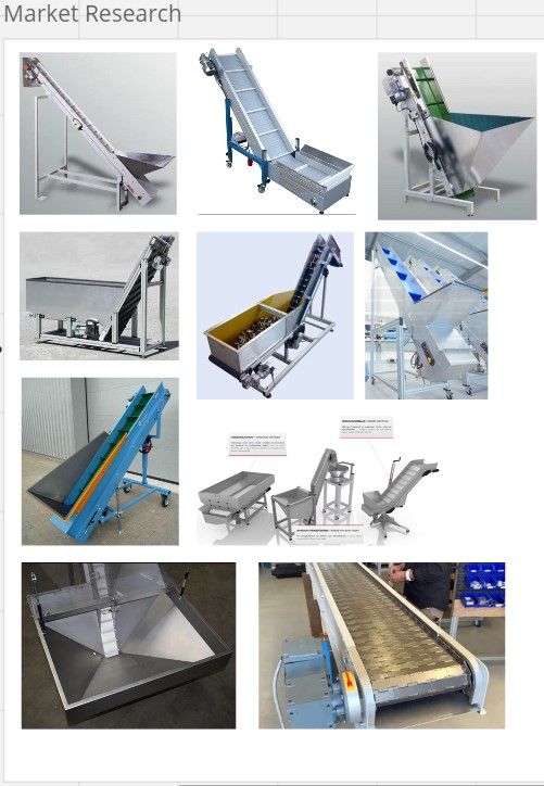
Step one: Scope and Market research
Published 2y. Edited 2yPublished about 2 years ago. Last edit about 2 years ago
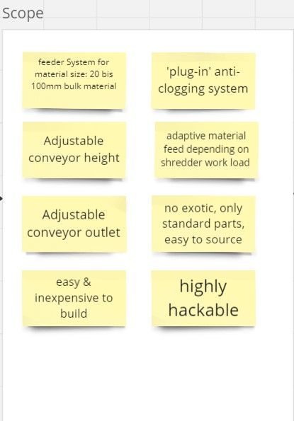
Okay, first of all, let's get the cards on the table and see what we wanna do and what not:
- feeder system for the shredder
- feedable material size 20-100mm
- adjustable conveyor height
- adjustable conveyor outlet
- easy and inexpensive to build
- 'plug-in' anti-clogging system
- adaptive material feed, depending on shredder work load
- no exotic parts, standard part preferred, easy to source
- highly hackable
Then, with this determination, let's look what is already on the market and get a little inspiration how things are solved state of the art.
%20--%3e%3csvg%20version='1.1'%20id='Calque_1'%20xmlns='http://www.w3.org/2000/svg'%20xmlns:xlink='http://www.w3.org/1999/xlink'%20x='0px'%20y='0px'%20viewBox='0%200%2027.2%2027.8'%20style='enable-background:new%200%200%2027.2%2027.8;'%20xml:space='preserve'%3e%3ctitle%3eicon%20redirect%20new%3c/title%3e%3cg%3e%3cpath%20d='M27.2,26.5c-0.1-5-0.3-10-0.4-15c0-0.7-0.6-1.2-1.2-1.2s-1.2,0.6-1.2,1.2c0.1,4.6,0.3,9.1,0.4,13.7%20c-3.9-0.2-7.7-0.6-11.6-0.4c-3.3,0.2-6.7,0.5-10,0.4C2.8,19.5,2.7,13.7,2.5,8c2.9-0.1,5.8-0.8,8.6-0.7c1.6,0.1,1.6-2.4,0-2.5%20C7.8,4.6,4.5,5.7,1.2,5.5c-0.6,0-1,0.3-1.1,0.7C0,6.3,0,6.4,0,6.6c0,0,0,0.1,0,0.1c0,0,0,0,0,0.1c0.2,6.6,0.4,13.2,0.5,19.7%20c0,0.6,0.4,1.3,1.2,1.4c3.8,0.1,7.5-0.2,11.3-0.4c4.4-0.3,8.6,0.2,12.9,0.4c0.6,0,1-0.3,1.1-0.7C27.1,26.9,27.2,26.7,27.2,26.5z'/%3e%3cpath%20d='M12,12.6c-0.2,0.7,0.2,1.4,0.9,1.5c0.7,0.2,1.4-0.2,1.5-0.9v0c0.6-2.2,1.4-4.5,3.1-6c1.3-1.2,3-1.9,4.7-2.7%20c-0.4,1.3-0.8,2.6-1.4,3.8c-0.6,1.5,1.8,2.1,2.4,0.7c0.8-1.9,1.5-3.9,2-5.9c0-0.1,0-0.2,0-0.3c0.3-0.6,0.1-1.5-0.7-1.8%20C22.3,0.4,20,0,17.7,0c-0.7,0-1.2,0.6-1.2,1.2s0.6,1.2,1.2,1.2c0.9,0,1.7,0.1,2.6,0.2c-1.7,0.8-3.4,1.7-4.8,3%20C13.6,7.6,12.7,10.1,12,12.6z'/%3e%3c/g%3e%3c/svg%3e)
2
Step 2: Morphological Box
Published 2y. Edited 2yPublished about 2 years ago. Last edit about 2 years ago
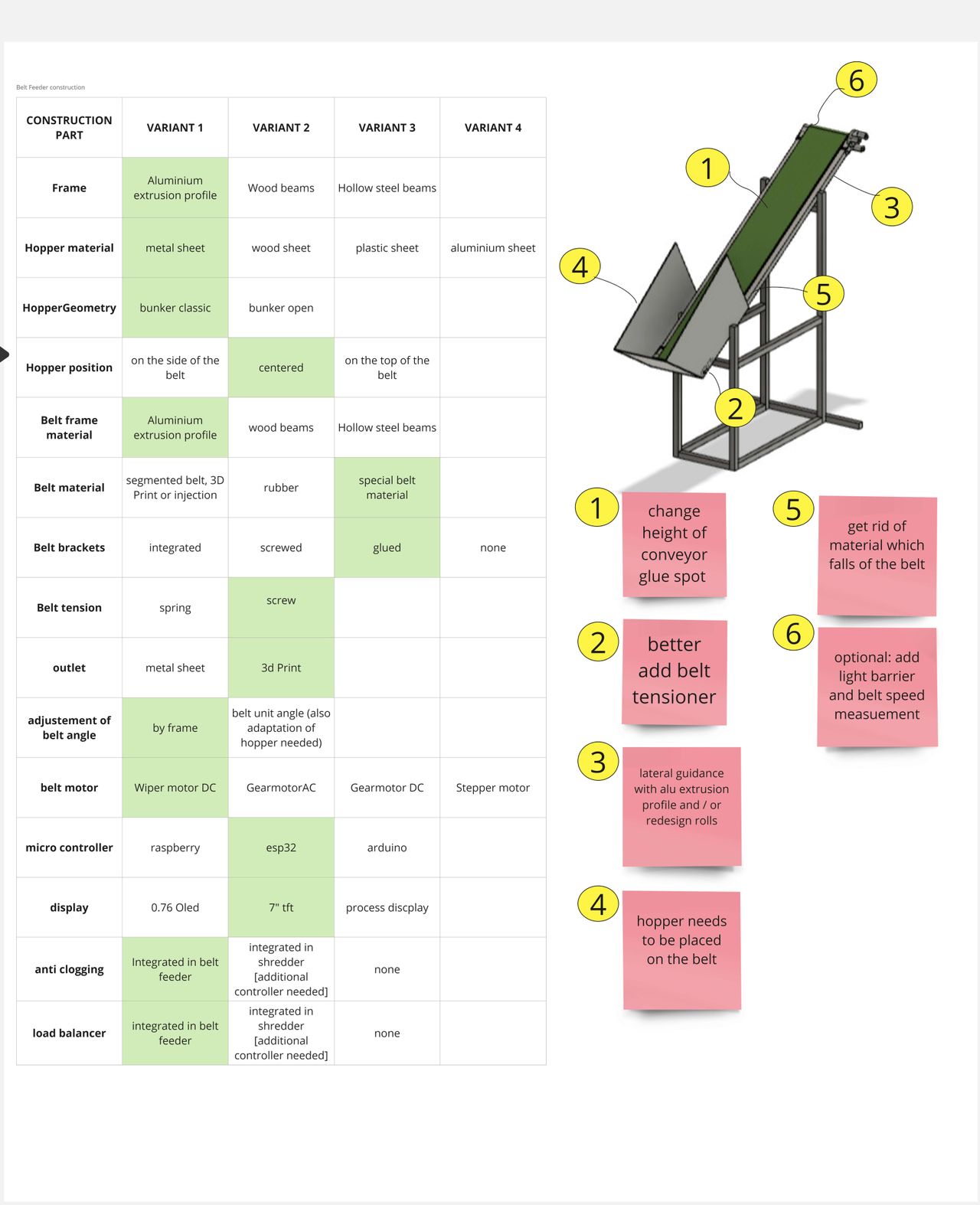
Now that we have an initial idea of the individual components, let's roll out the knowledge into a morphological box.
On the y-axis, the box contains all the main parts of our belt feeder and on the x-axis we fill in all the possible variants to build the components.
For example the Frame, as component, can be made out of aluminium extrusion profiles or wood beams or hollow steal beams or even recycled palstic beams.
By progressing in the project, we can also add some additional information to each variant.
From this point on, making the first design study / prototype, we can go through each component in the box and decide, which variant to take.
-190bd473098.jpg?width=1280&resize=contain)
3
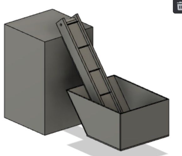
Step 3: Design Prototyp
Published 1y. Edited 1yPublished almost 2 years ago. Last edit almost 2 years ago
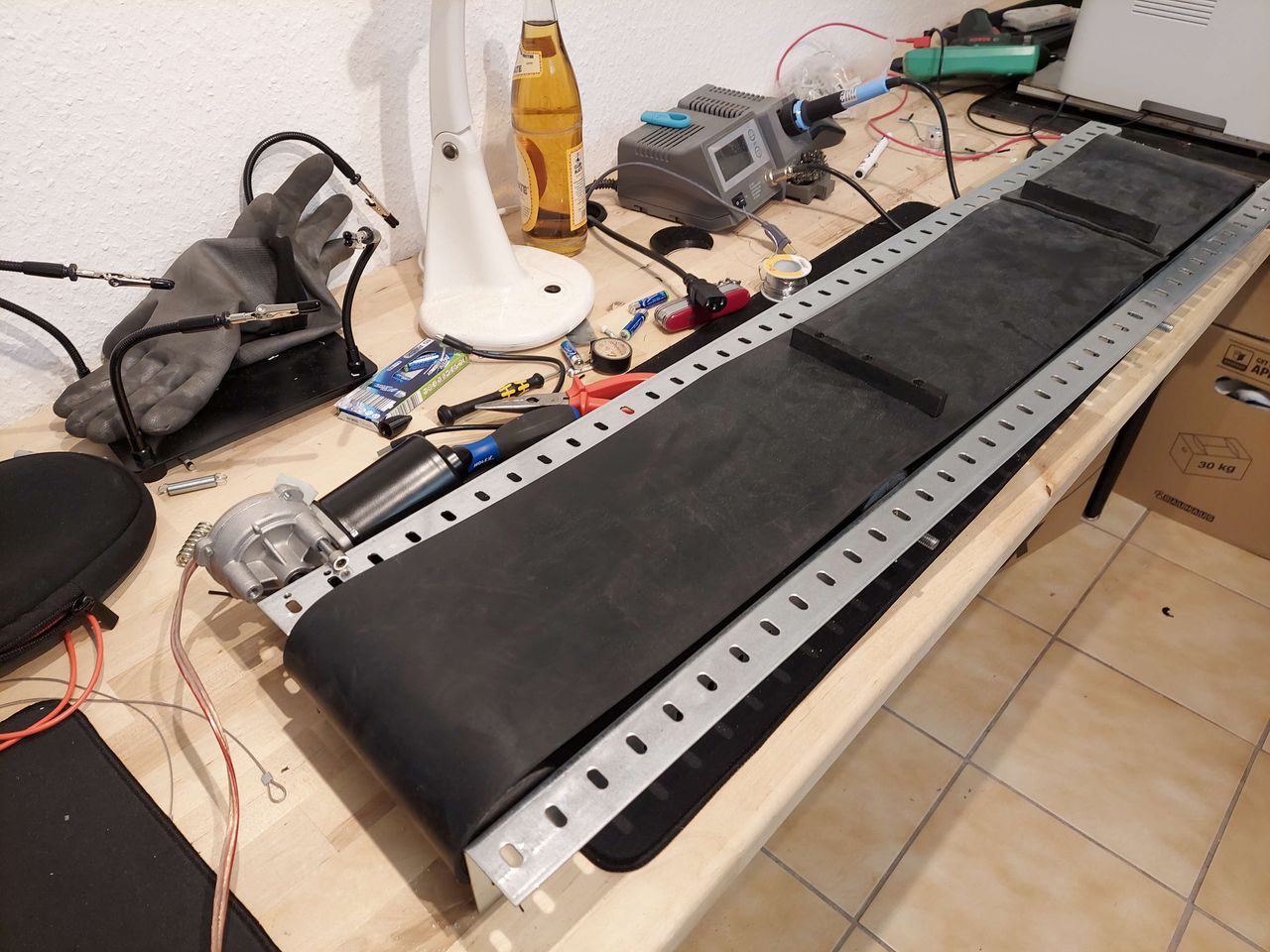
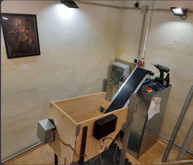
The design prototype served as the basis for the application for the funding project a few months ago. Nevertheless, thematically it fits very well into the project process at this point, as the first variants of the main components, such as stepper vs. DC motor, can already be tested. You also learn how the components behave as an overall system. The knowledge gained is then immediately recorded in the morphological box and is used to create the next, improved iteration.
-1913abc3fc7.jpg?width=1280&resize=contain)
4
Iteration 1
Published 1y. Edited 1yPublished almost 2 years ago. Last edit over 1 year ago
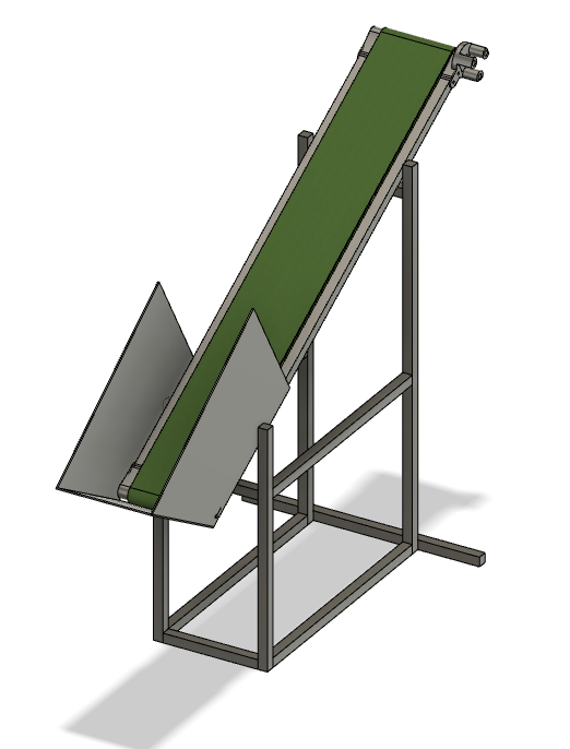
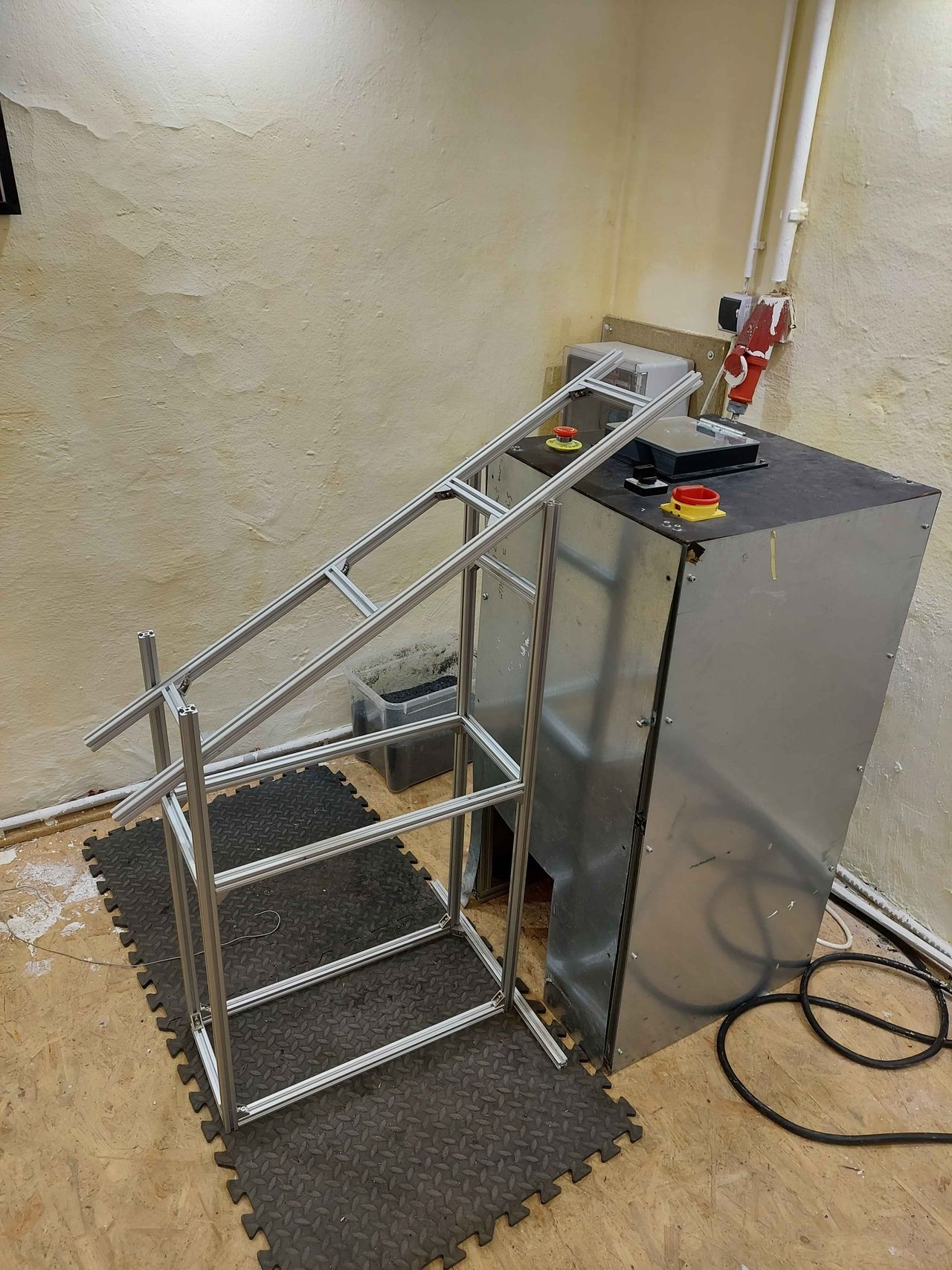
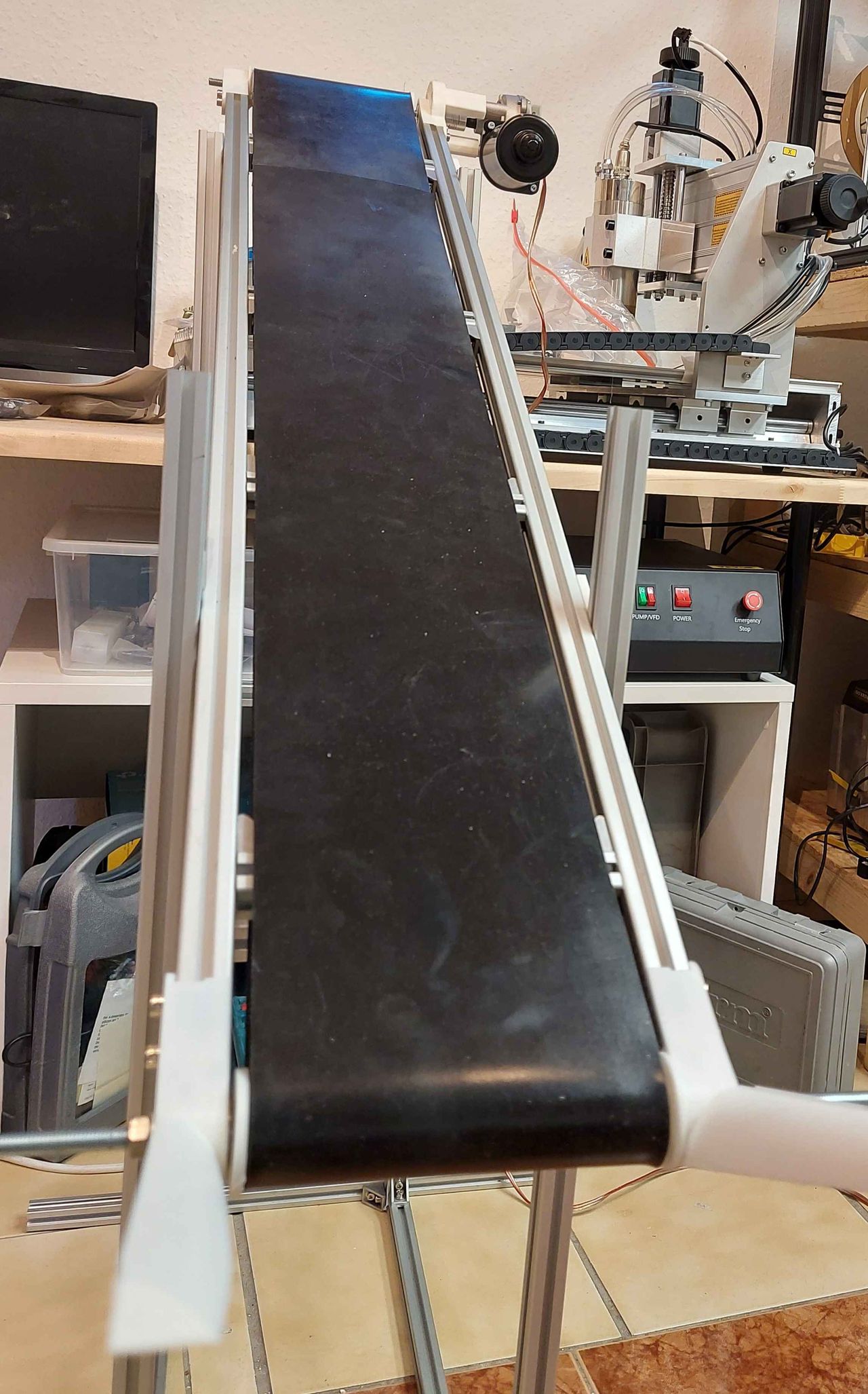
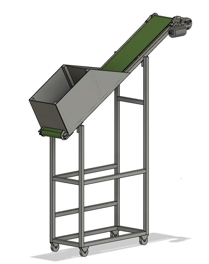
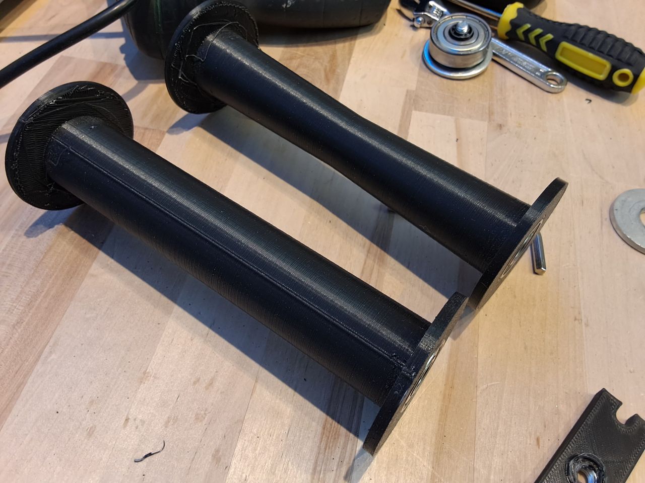
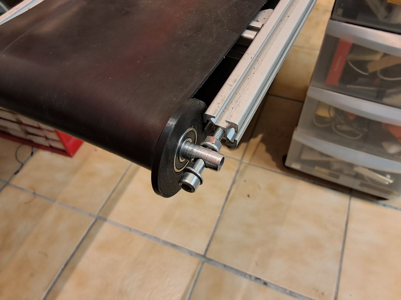
With the findings from the prototype test, the next stage of development continues. Visually, you can already see a clear difference. Instead of wood and steel, extrusion profiles and printed parts are used. The frame and belt have been separated so the conveyor height and angle can be easily adapted to the shredder. In addition, the material supply is directly mounted on the belt, which also simplifies assembly. The 3D printed components allow easy adaptation for the next iterations. The rubber conveyor belt is retained, but in a thinner and fiber-reinforced version.
The research topics in this iteration were about which rubber glue works best, which traction roller geometry to use, the performance of different motor controllers, software development, power supply and mechanical structure.
5
Testing Iteration 1
Published 1y. Edited 1yPublished over 1 year ago. Last edit over 1 year ago
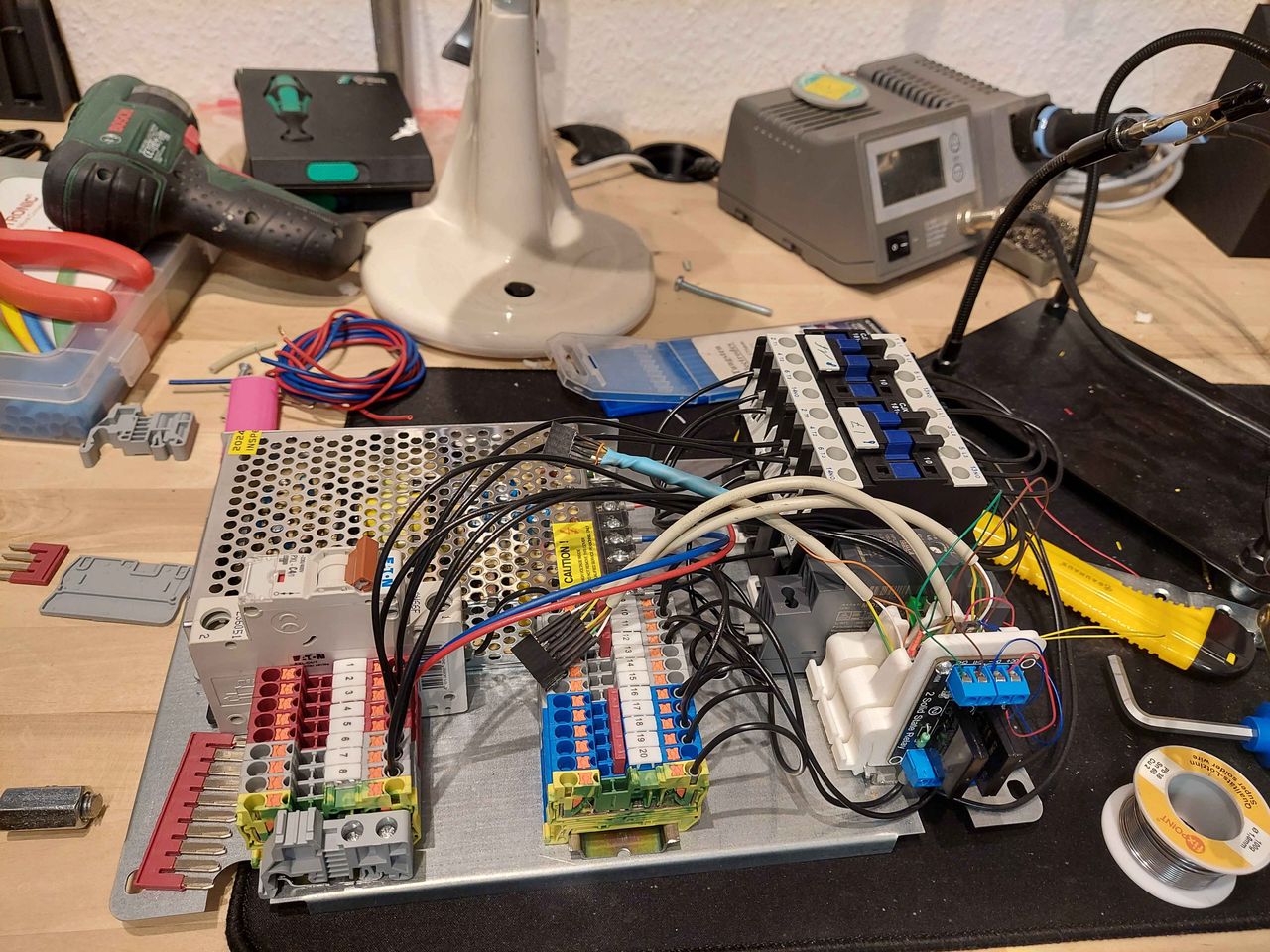
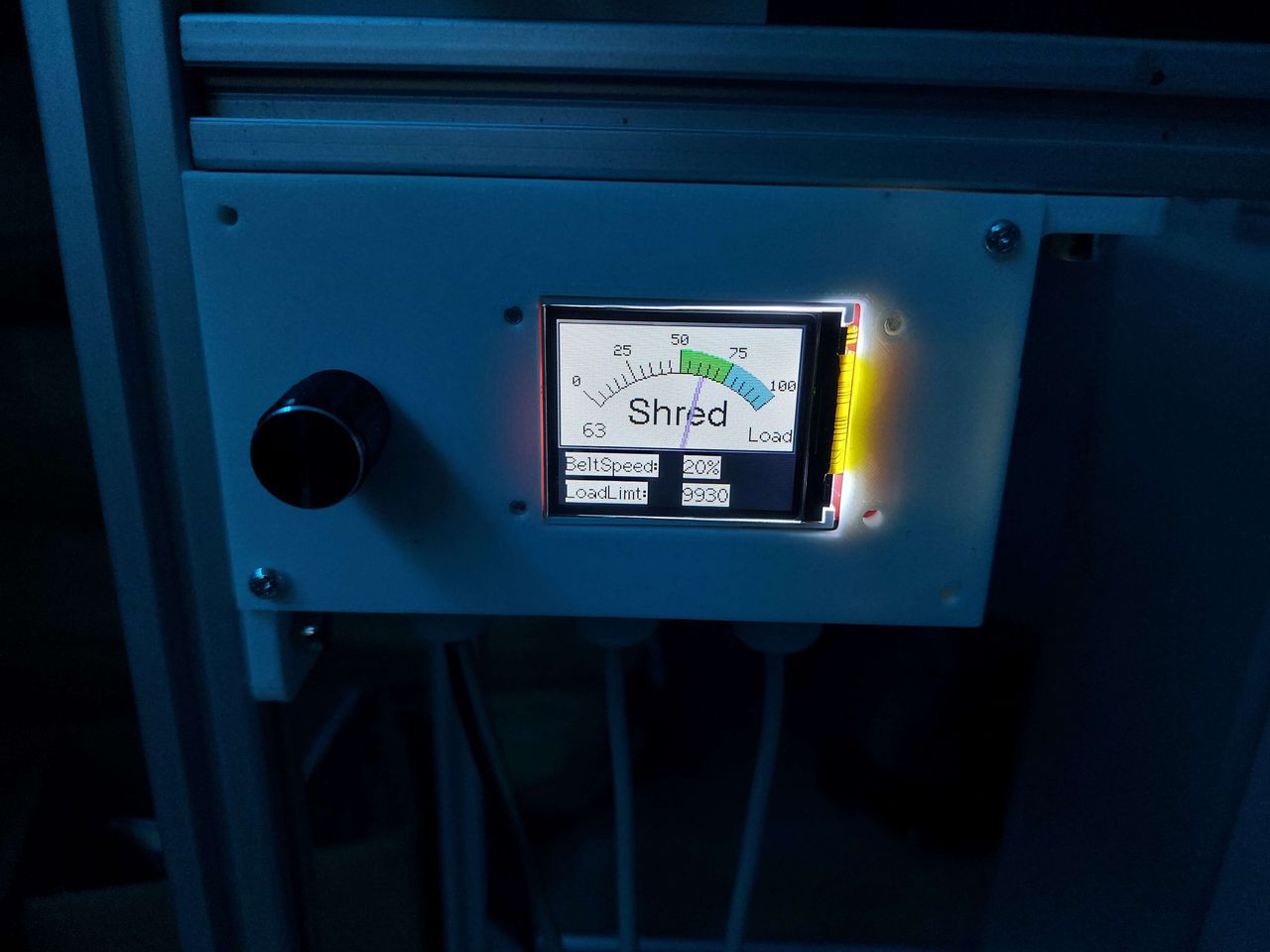
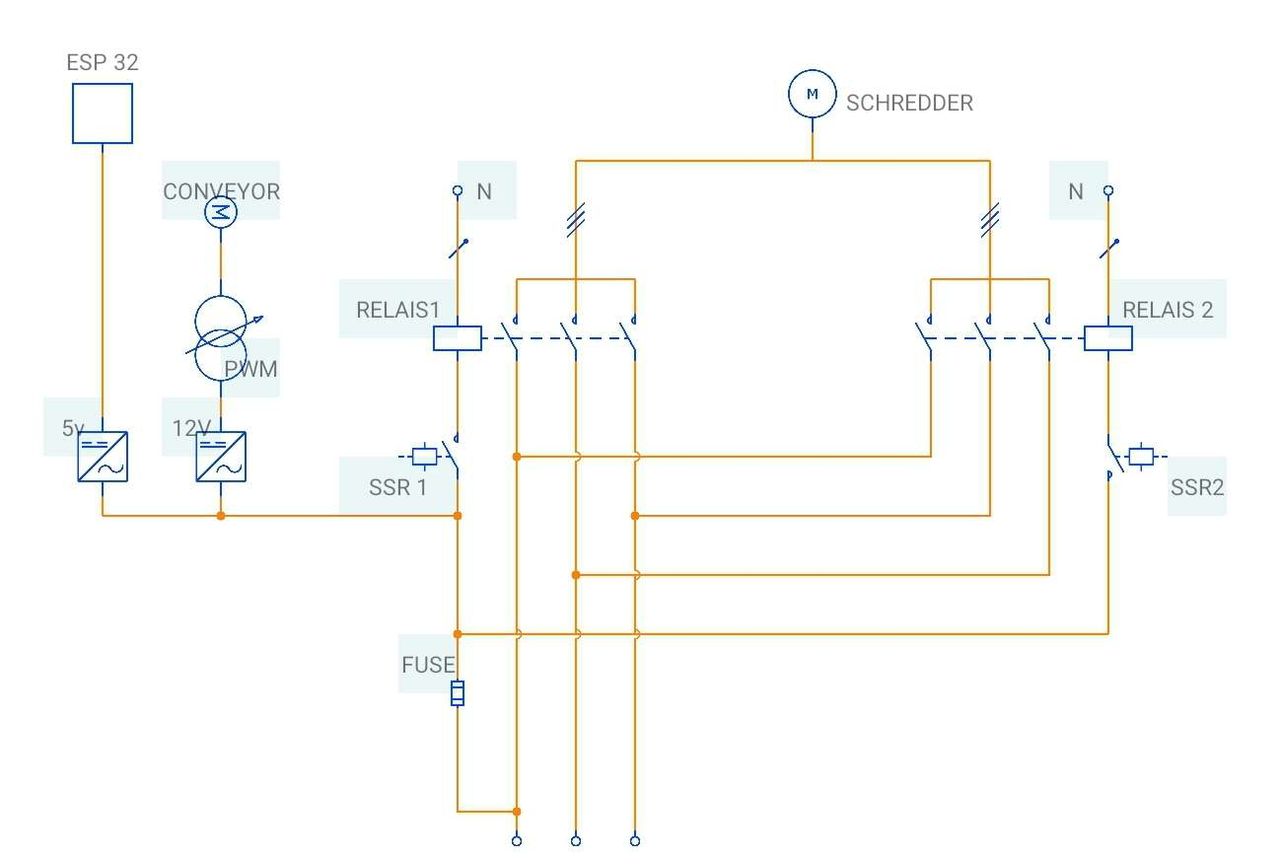
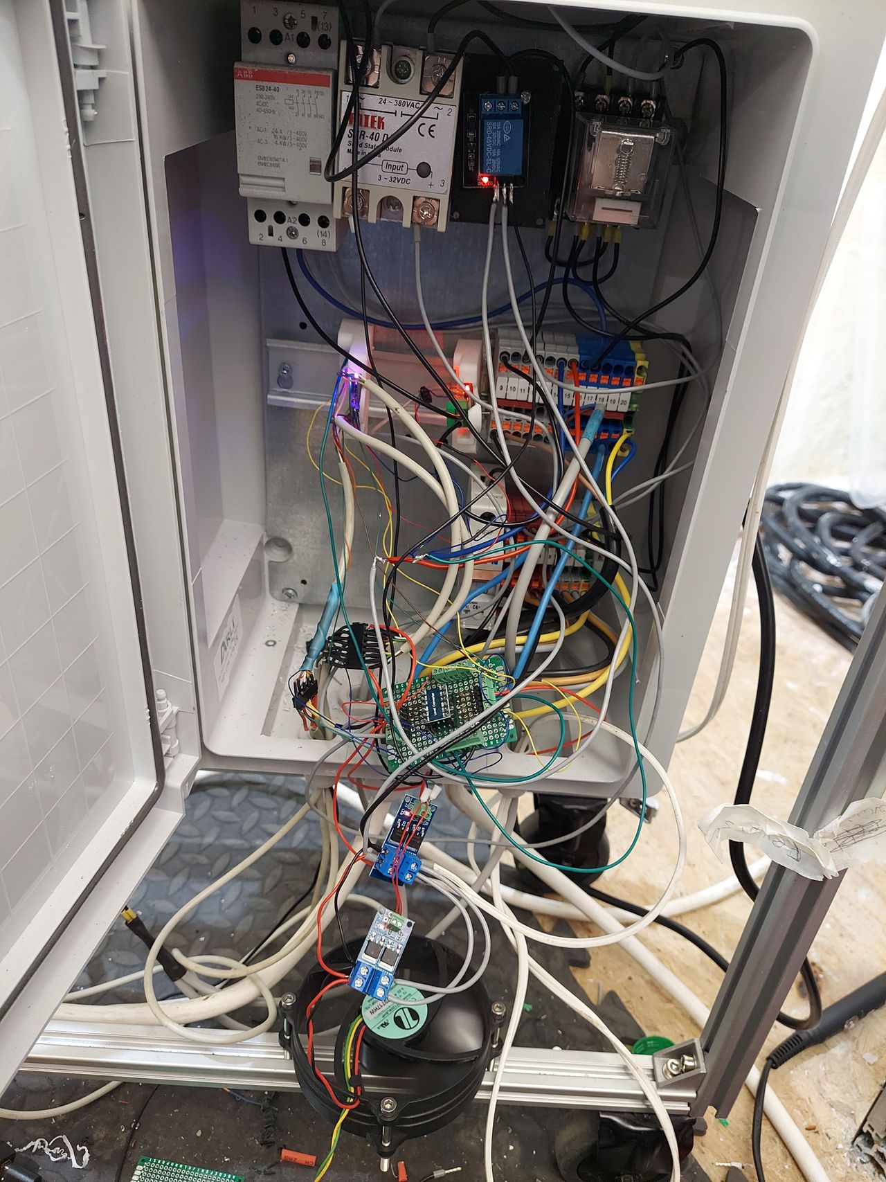
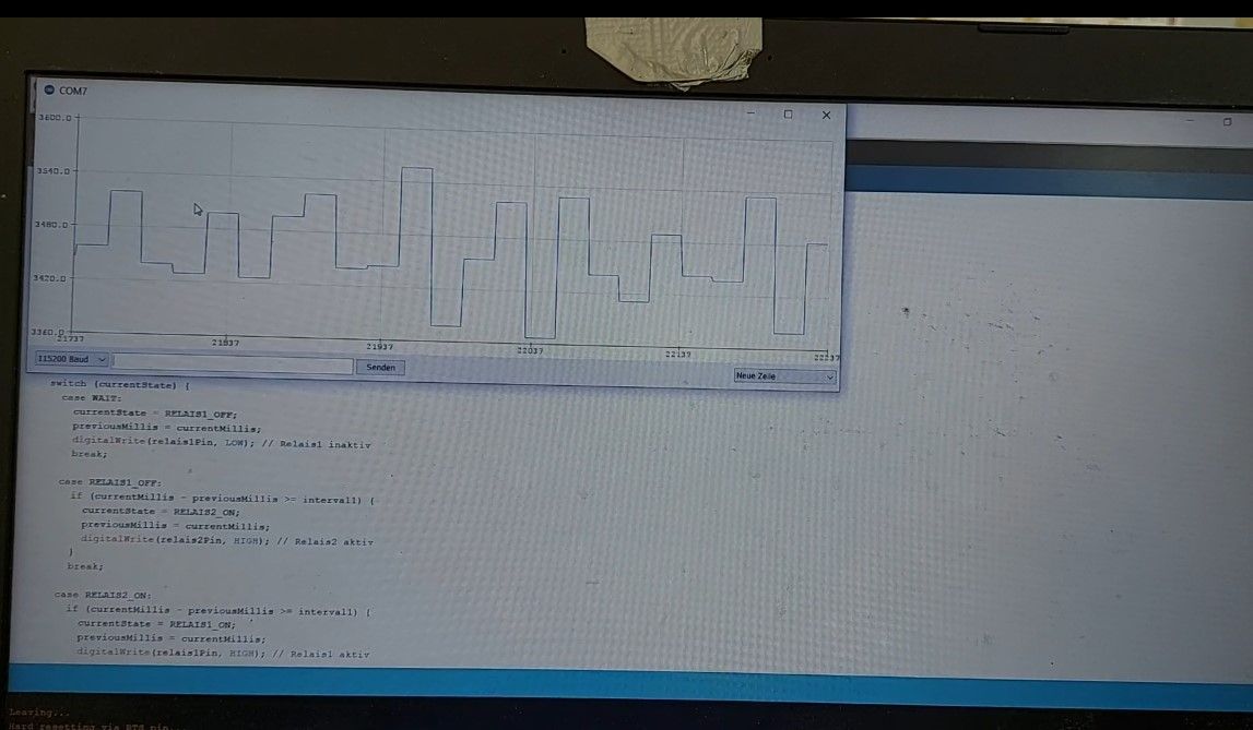
Phew, the test phase brought a lot of to-do's again. Starting the belt was okay, but only that. The first problem was measuring the shredder load, which needs a super stable 5V to work well. So the cheap power supply had to be replaced with a more stable one. With good load alignment, the next problem occurred when the shredder was switched to rewind mode, as the large relay caused very strong electromagnetic interference. To remedy this, the relays were replaced with SRR's, which also did not work well, and then finally with smaller relays. In the course of this, the electrical wiring of the relay was changed and a snubber was added.
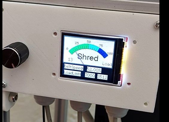
The tests were continued with this setting. Again, the winding process did not work well, but after the software was rewritten, the belt stopped on overload and the shredder did its job to avoid clogging. After a few hours of testing, the controller for the belt motor failed and had to be replaced with a different model. With this setting, the feeder worked quite well. So there was time to refresh the software for the load visualization.
The next problem was that even at lower belt speeds, the amount of material on the belt was too high for the shredder to process. To remedy this, a redesign of the hopper is required, which is done in iteration2.......
6
Start Iteration 2
Published 1y. Edited 1yPublished over 1 year ago. Last edit over 1 year ago
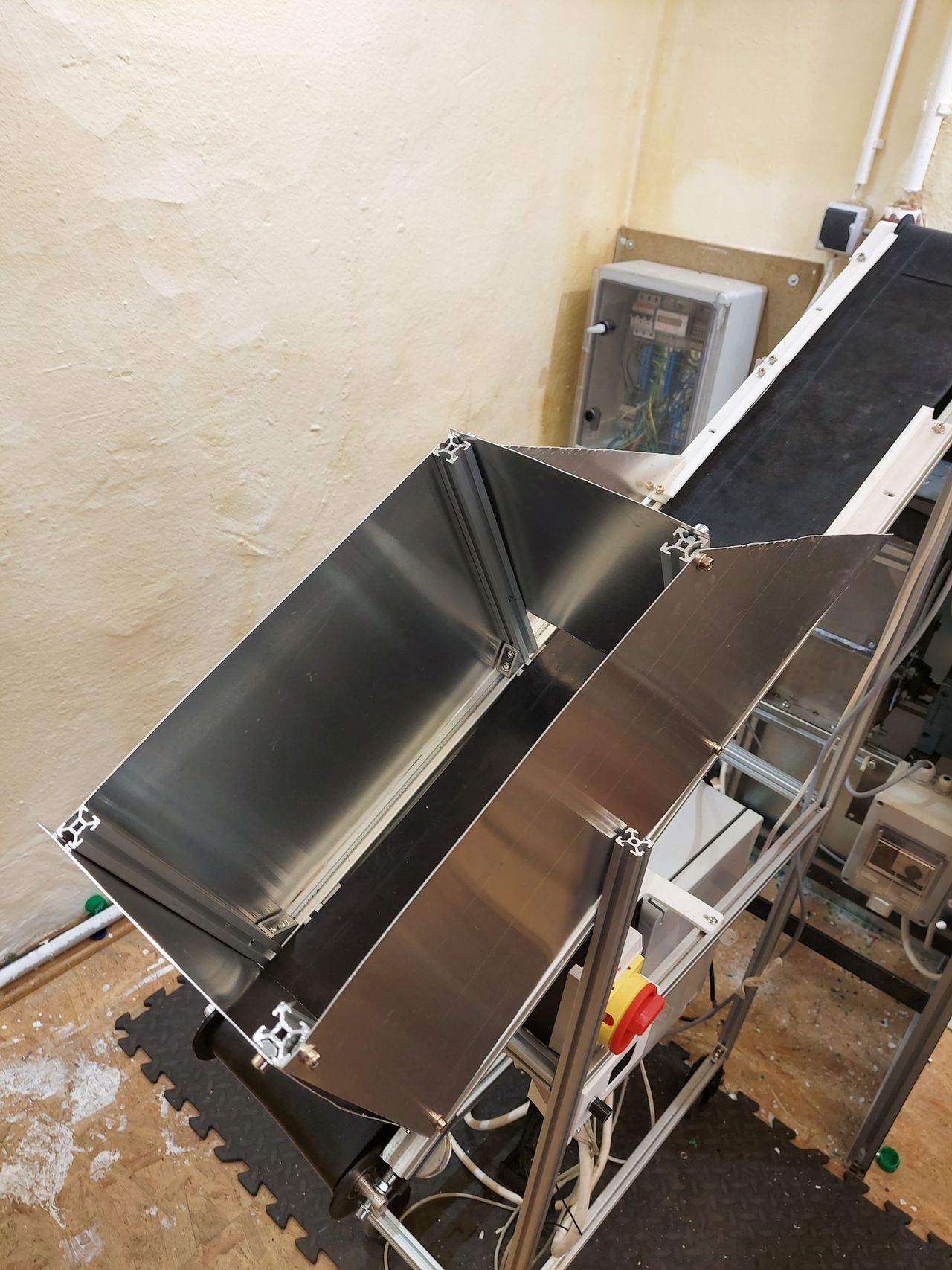
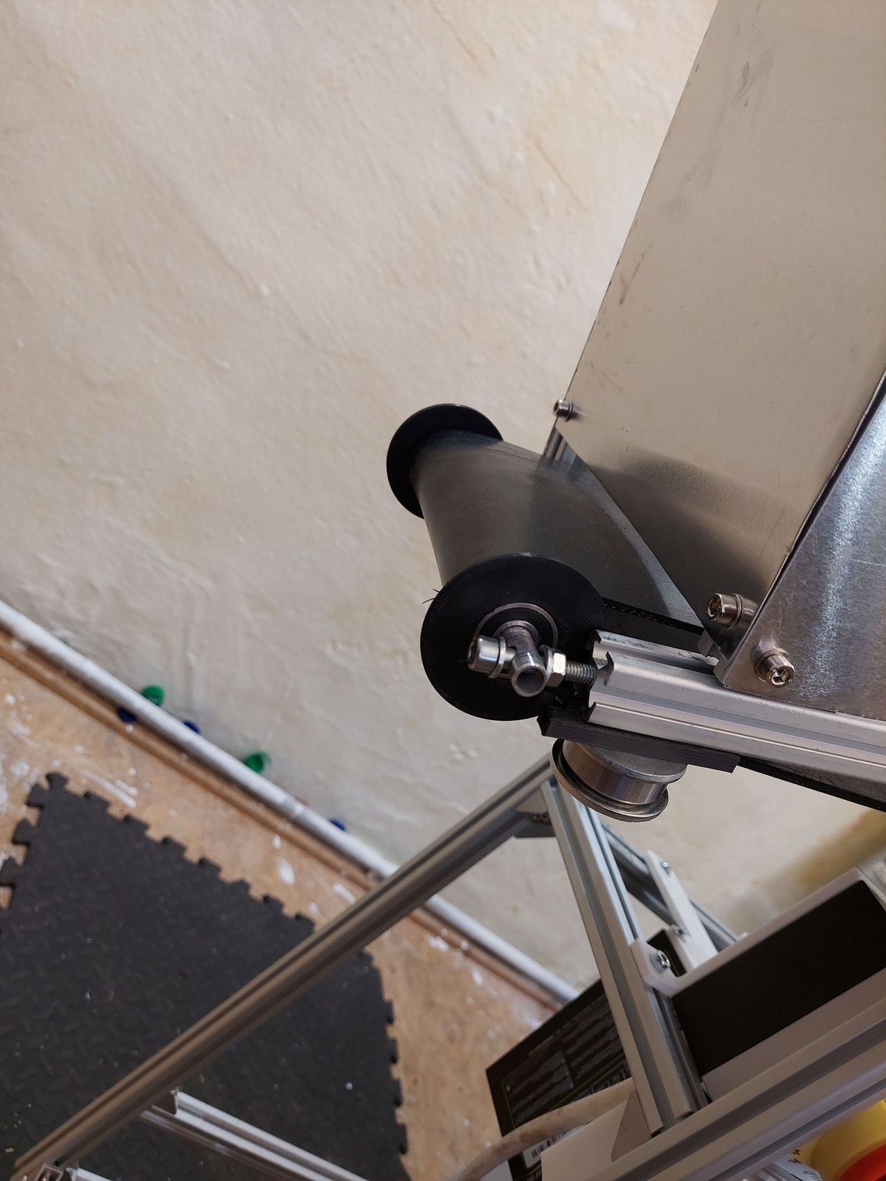
The revised model now has castors under the frame. In addition, the hopper has been redesigned to ensure better distribution of the material on the belt and to improve manufacturability. The guide roller is now slightly conical to allow the belt to run more centrally. In addition, the belt can now be easily tensioned using side screws
Software changes include an adaptation of the load measurement and visualization.
With regard to the electronics, the direction of rotation is now switched via one switching relay and one changeover relay instead of two switching relays.
attached file: Version 2.0 of the machine
7
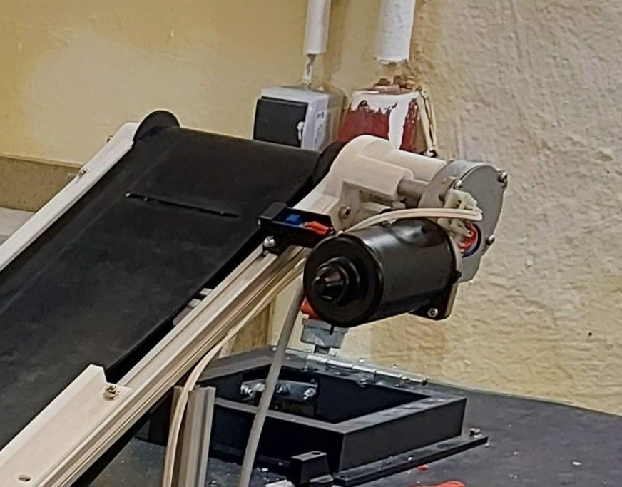
Iteration 2 build up and first tests
Published 1yPublished over 1 year ago
Iteration 2 comes to live, the reworked driver rolls have additional track roller. The new hopper is bigger an sits directly on the belt with an additional inner plate to hold back material. To prevent the schredder from overload, there is also an light barrier implemented, which stops and starts the belt in intervals when it detects material to feed the shredder only with small portions of material. Therefore the software needed a major update. The initial tests have shown good results but further testing may require asjustements

8
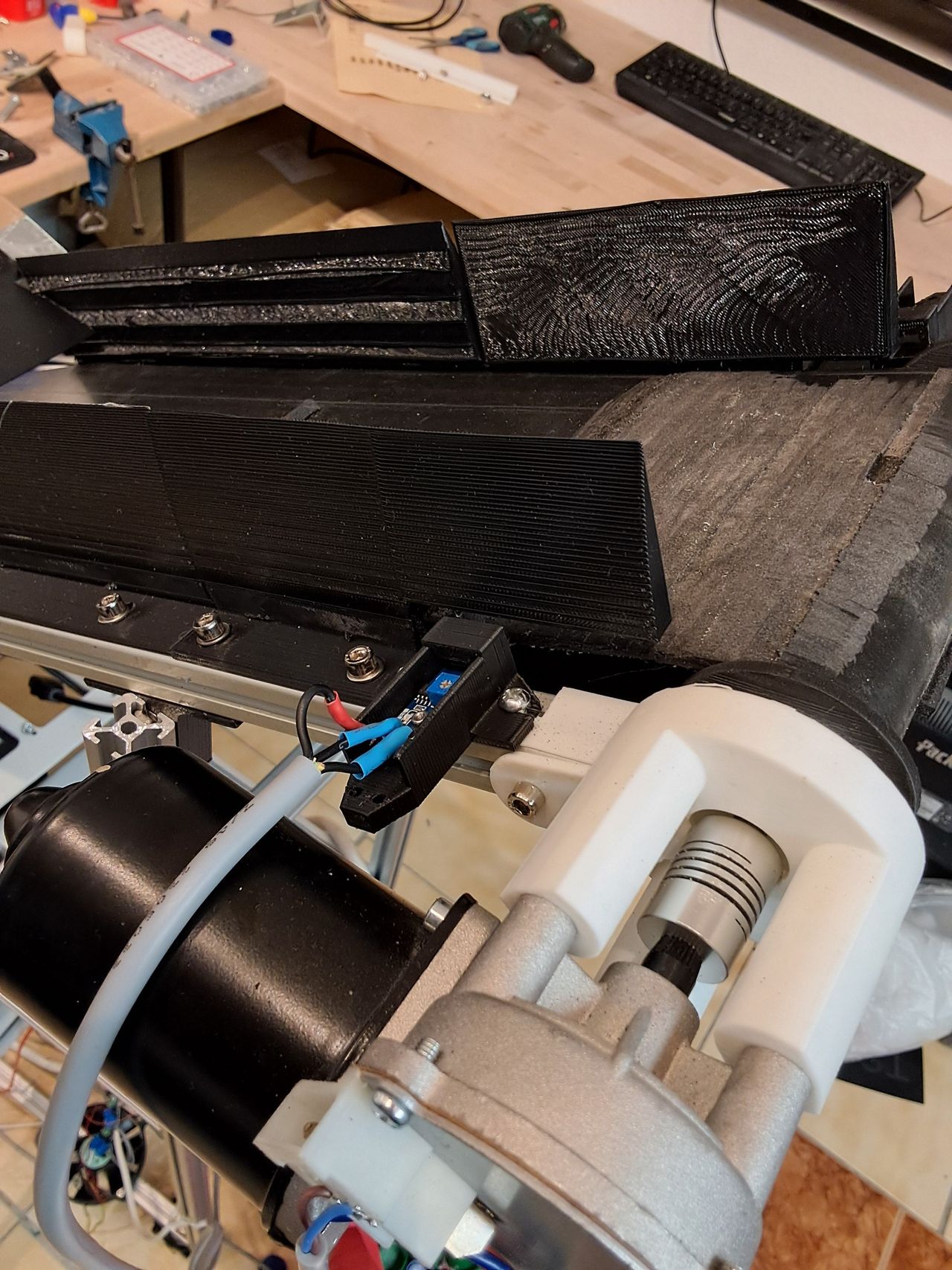
Testing the Hopper Design
Published 1y. Edited 1yPublished over 1 year ago. Last edit over 1 year ago
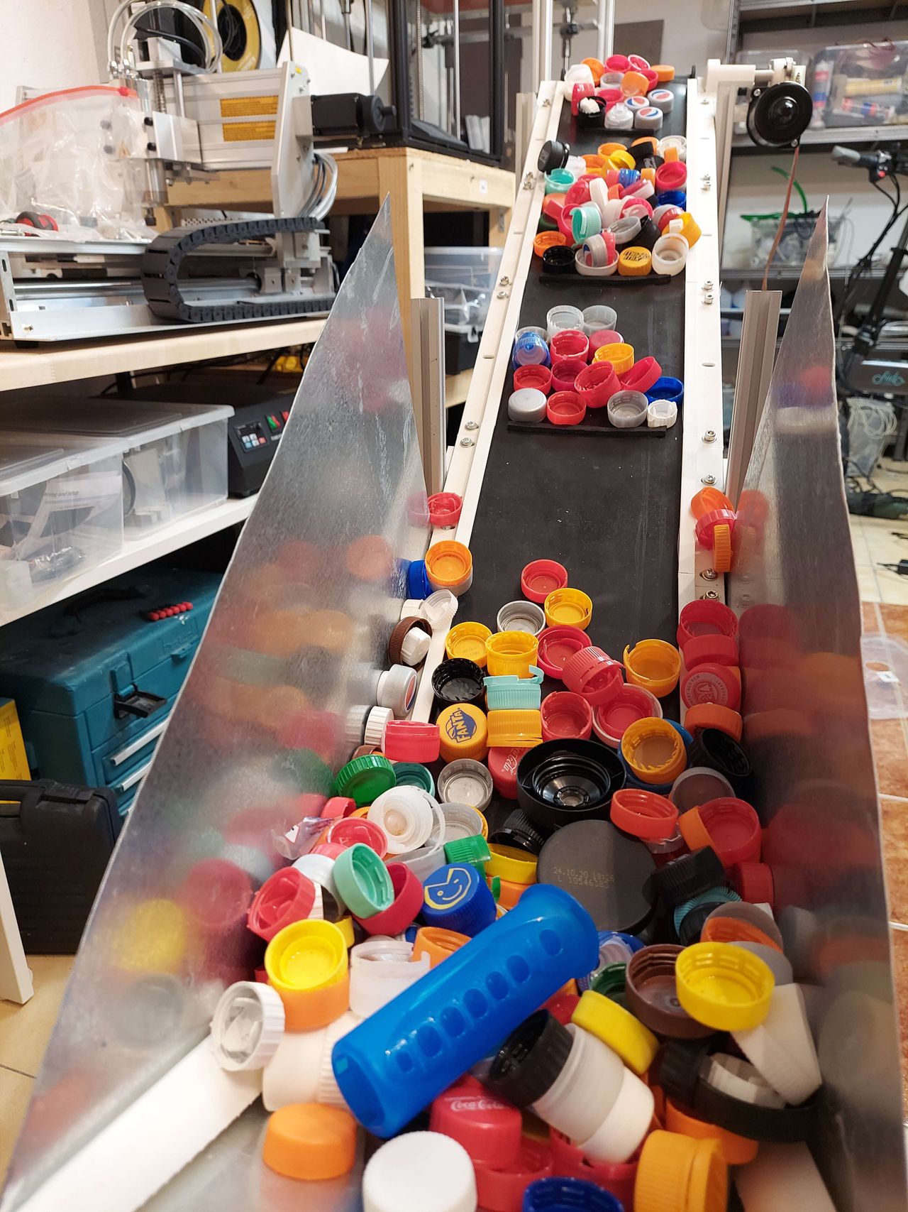
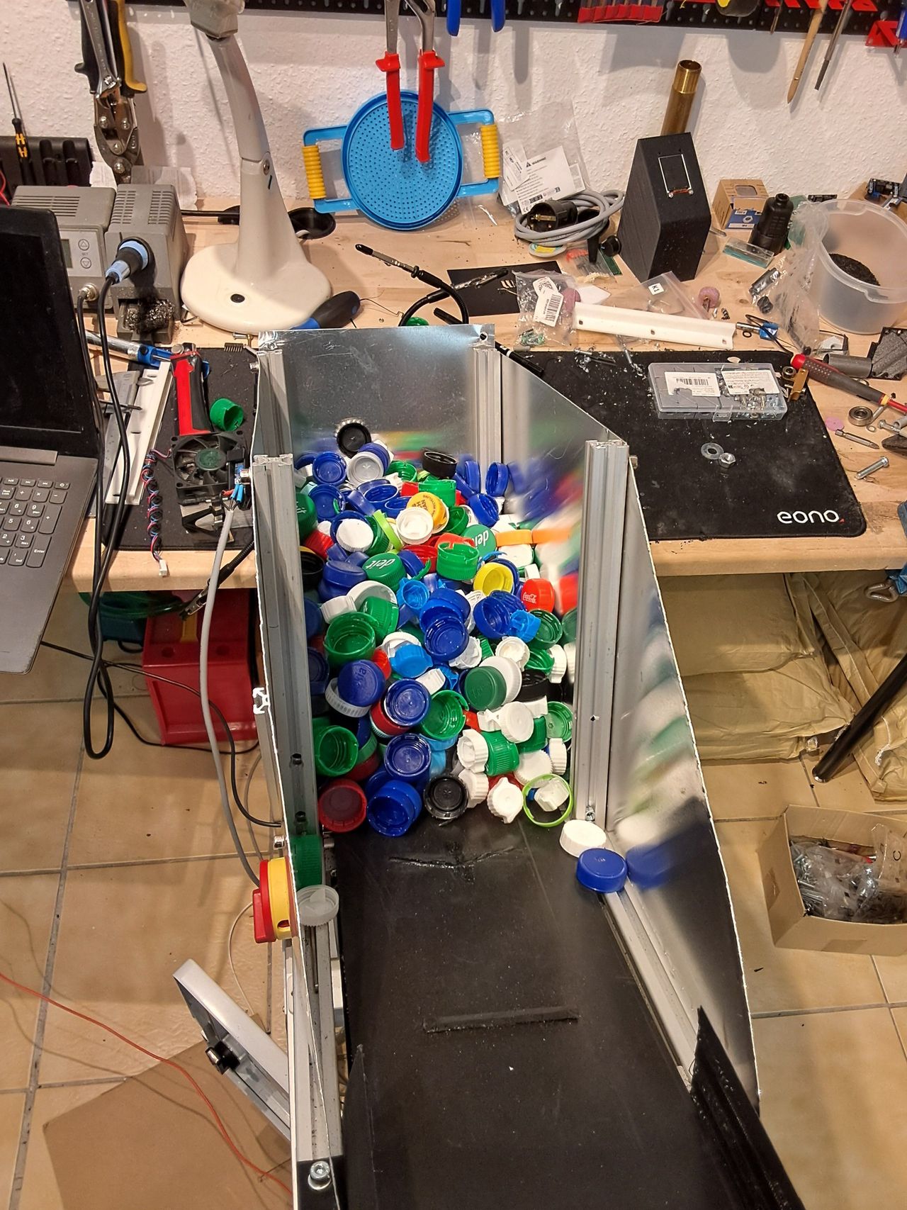
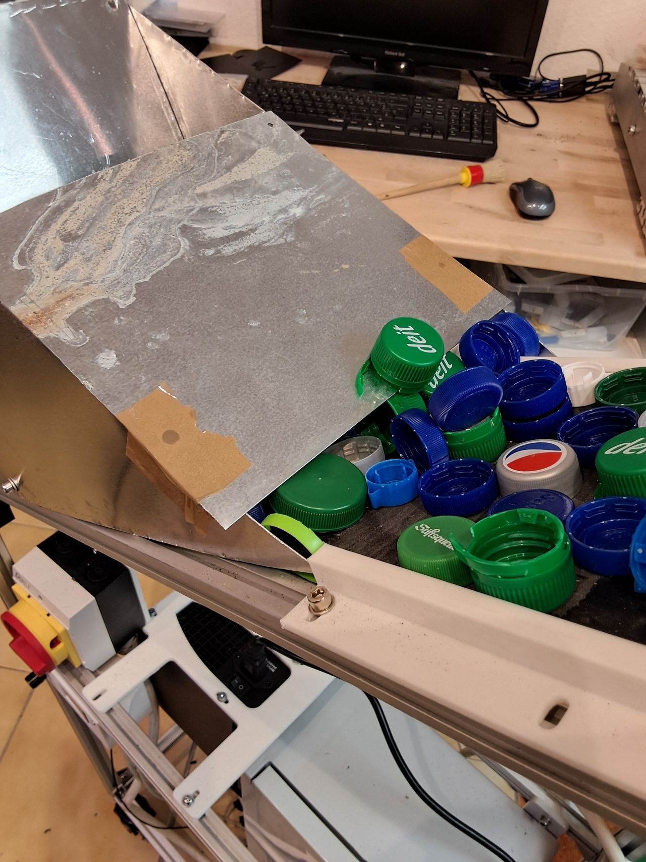
Let's test the new design of Iteration 2. As mentioned in the last post, the hopper is placed directly on the belt.
1) The first test showed good material transfer, but the amount of material on the belt was too large.
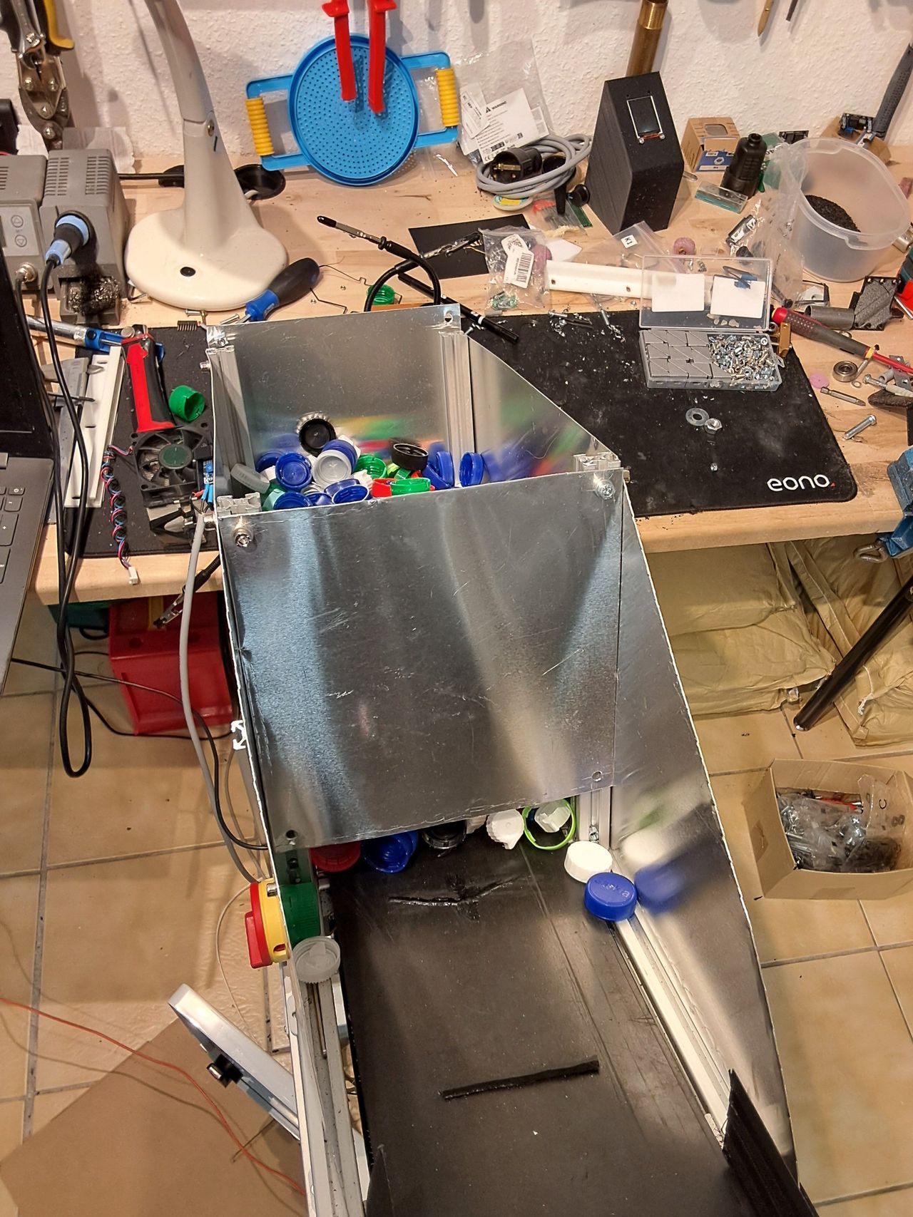
2) Therefore, a plate was added to reduce the amount of material transferred. However, if the distance between the belt and the plate was too small, the caps tended to clog underneath. So all in all, it was helpful, but could not reduce the material flow sufficiently.
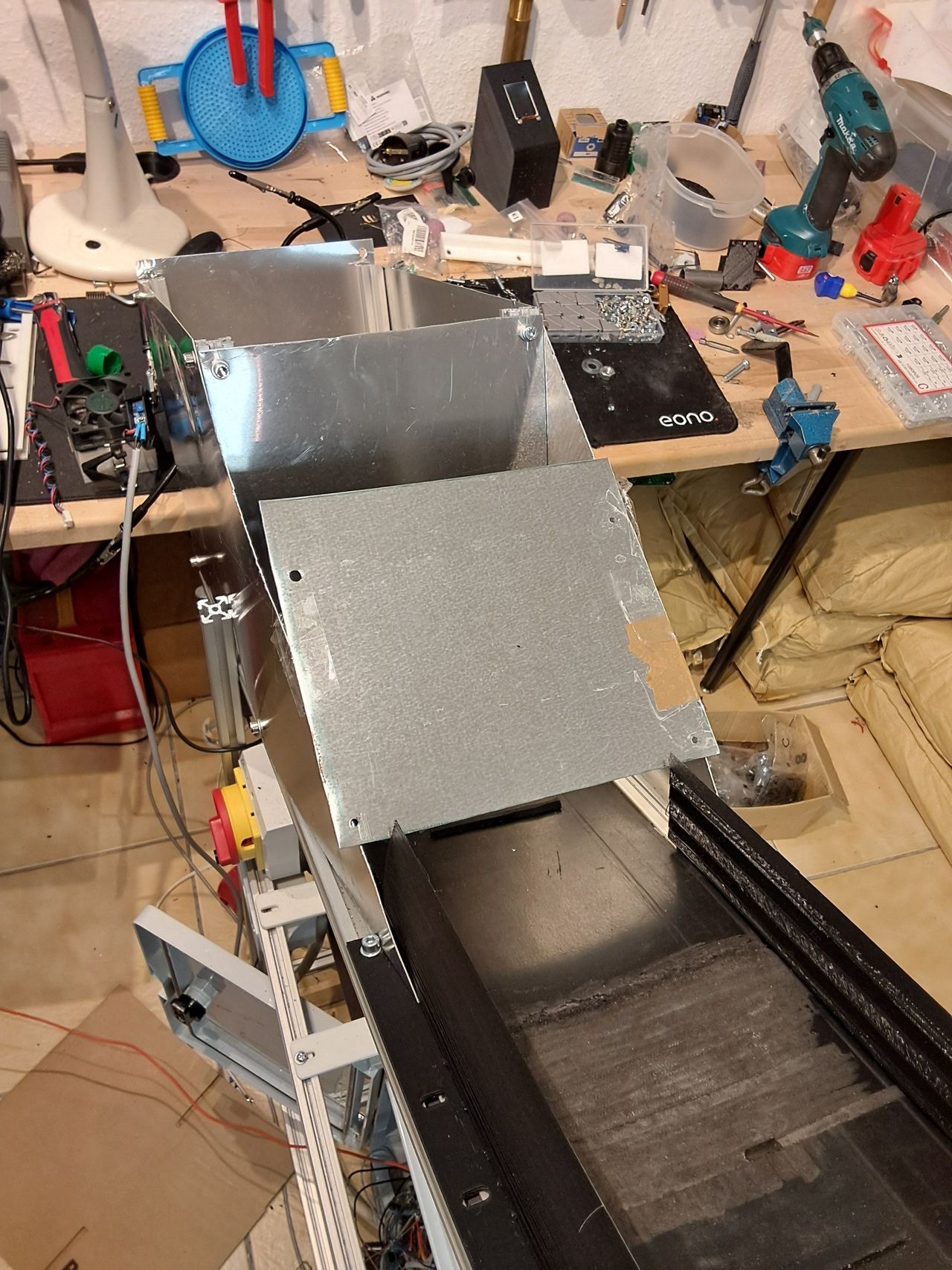
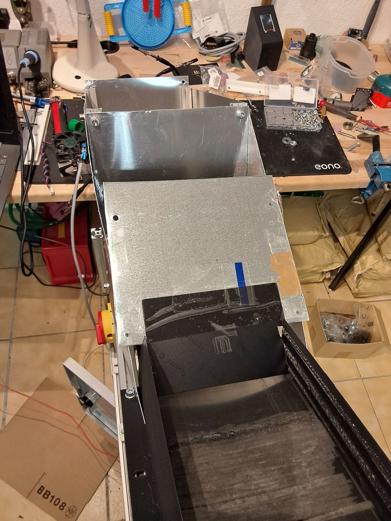
3) In addition, a second plate was added to the outlet side of the hopper, which proved to be too stiff as the material underneath could clog.
4) So the space between the plate and the belt was enlarged and a thin plastic sheet was added, which works quite well due to its flexibility. It holds back stacked caps, but is also flexible when the caps are wedged together.
5) A smaller but still annoying problem was caps falling over the side boundary. Therefore, the side walls were also redesigned with other materials in mind and increased in height, which now works well.
attached file: v2.1 includes the separator sheet & the side wall
9
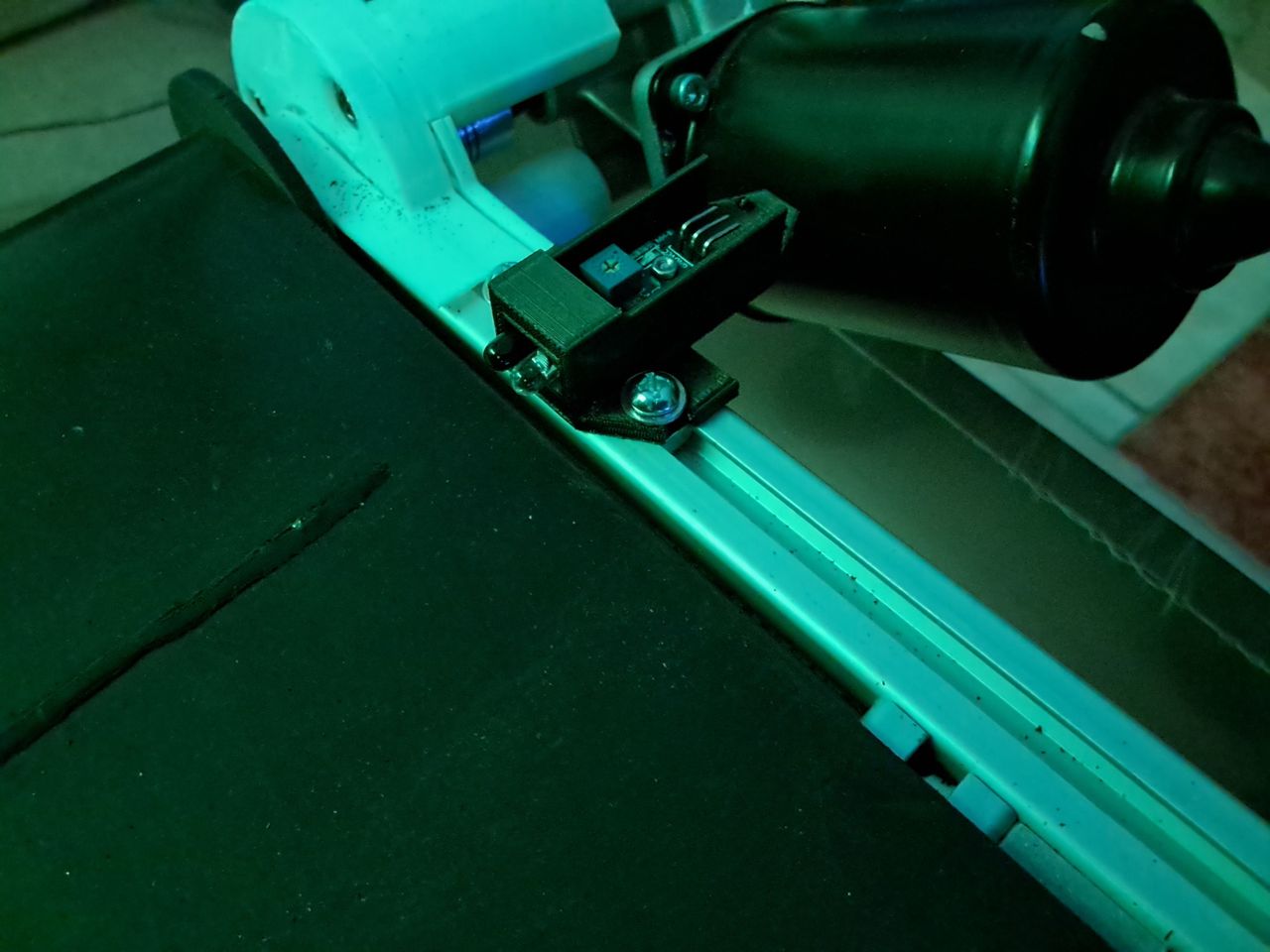
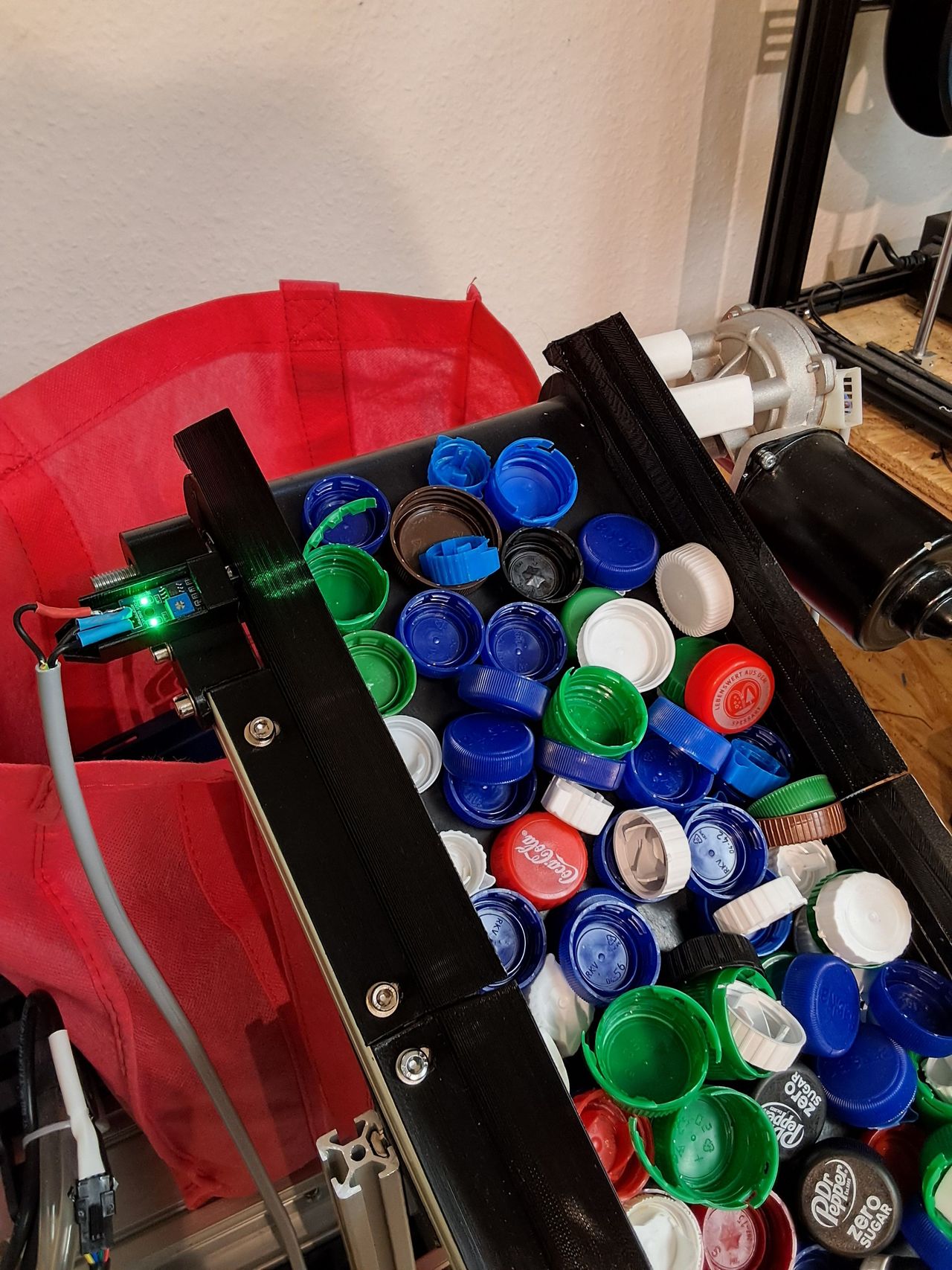
Iteration2: Test and adapt the light barrier
Published 1y. Edited 1yPublished over 1 year ago. Last edit over 1 year ago
The shredder we use to carry out the tests only has a small capacity. The conveyor belt also has an integrated load control, but as you can imagine. The load increases when the material is already in the shredder, which can lead to problems.
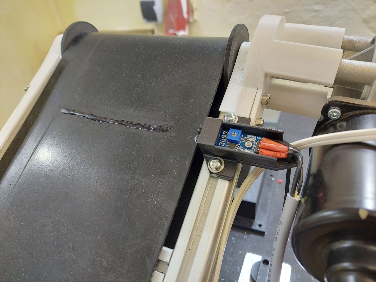
Therefore, the project needs a second control mechanism to control the material feed before it enters the shredder. An inexpensive photoelectric sensor is perfect for this task. It simply detects crossing objects and sends a signal to the microcontroller. Based on this signal, the belt is switched off for a certain period of time to reduce the material feed.
The tests have shown that a toggle switch works quite well. If an object is detected for longer than 1s, the belt stops for 10s.
A fully loaded belt constantly triggers the barrier so that it runs for 1 second, during which material is transported into the shredder, and then stops for 10 seconds so that the shredder can process the material. Then the cycle starts again.
The tests have shown that it also makes sense to position the barrier as close as possible to the end of the belt, as this minimizes the amount transported in cases where no new material is transported.
For this reason, the side wall and the mounting bracket have been redesigned.
Attached File: V2.2 includes the light barrier mounting
10
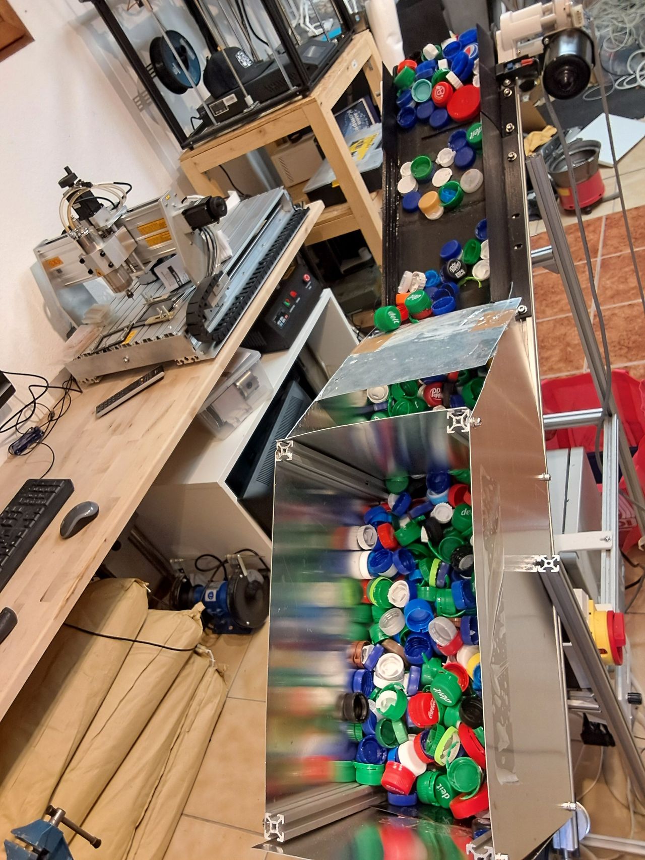
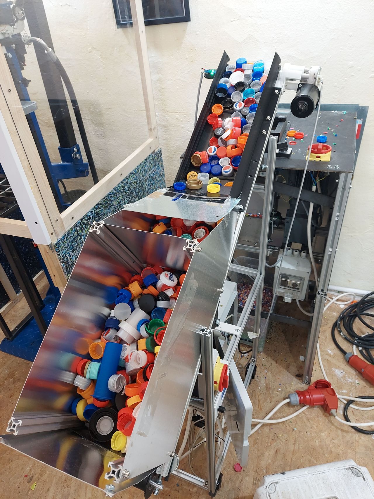
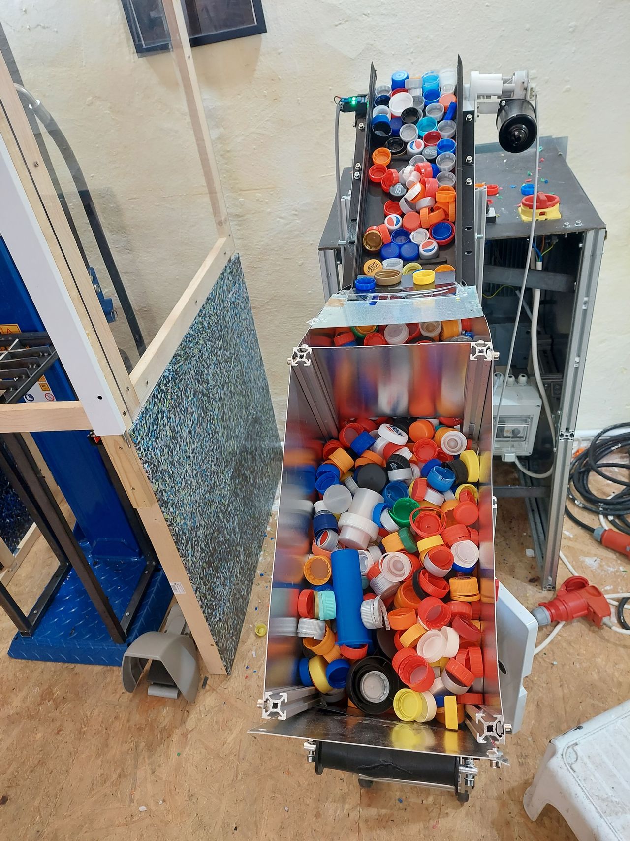
Iteration 2: Final Test session
Published 1yPublished over 1 year ago
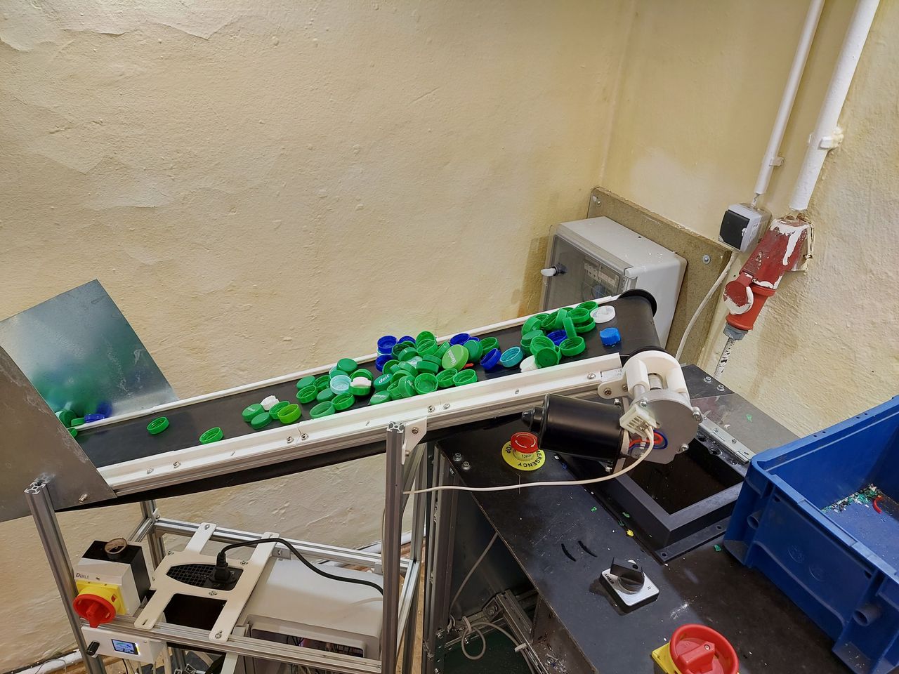
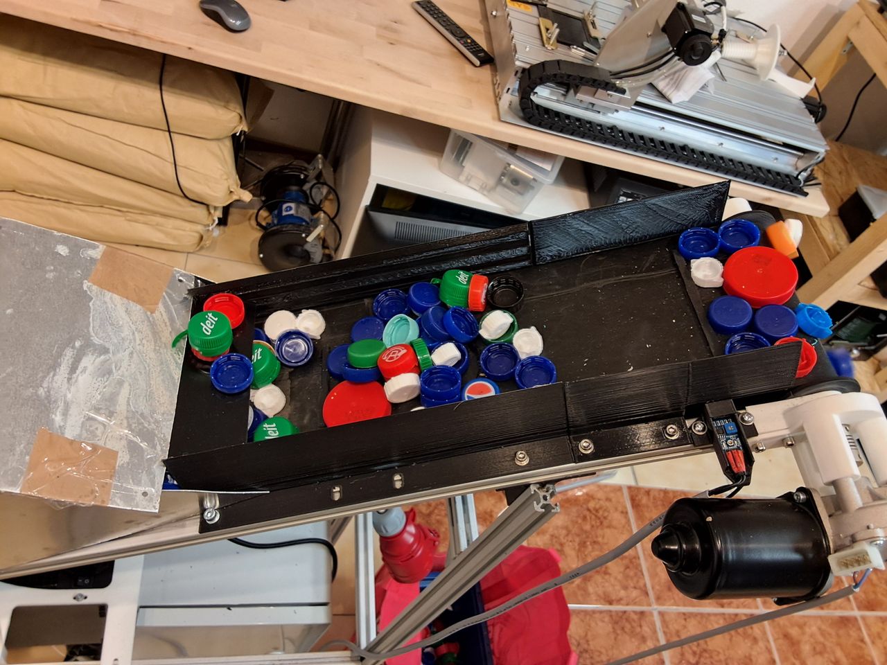
Final session, conveyor belt interacting with the shredder. The hopper is completely filled and the belt transports the material to the shredder. When the light barrier detects material, it stops the belt for a few seconds, giving the shredder time to process the material.
The set-up has worked quite well so far. With the lightbarrier start/stop system, the shredder has only had a couple of jams, which were automatically cleared by the belt controler, which stopped the conveyor and rewound a few revolutions of the shredder.
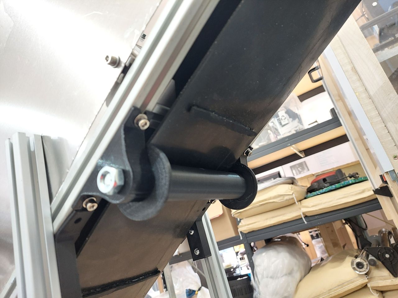
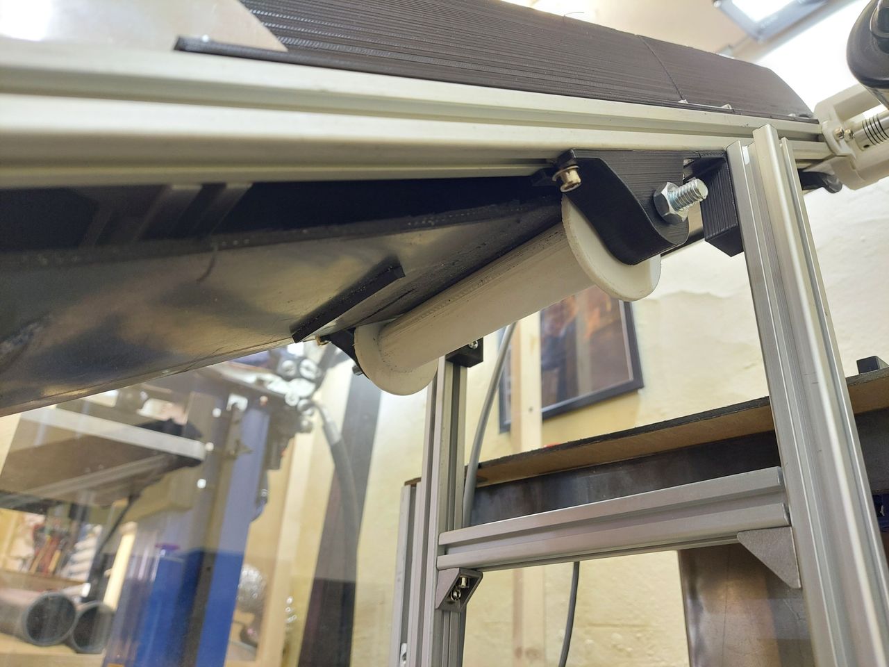
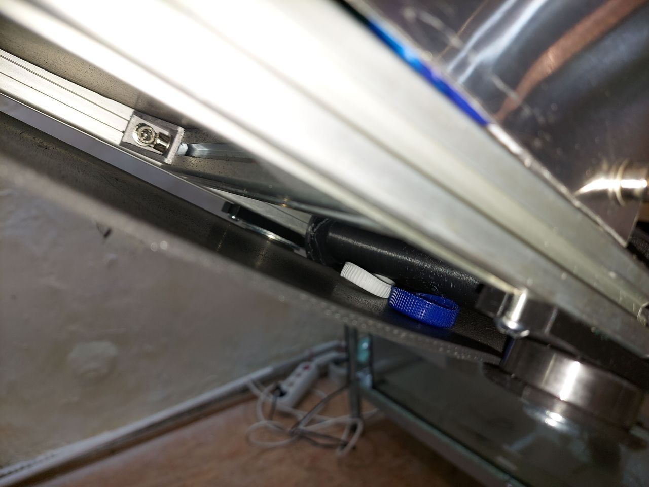
On the mechanical side, two rollers were added to the underside of the belt to make it straighter.
During testing, some minor problems were encountered. Some bottle caps got stuck between the roller and the belt. So for the next iteration, the gap between the frame and the belt needs to be closed.
The position of the light barrier also needs to be adjusted slightly to make it more robust against interference from the belt itself.
11
Iteration 2: Final Test session video
Published 1yPublished over 1 year ago
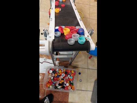
A short video shot during the test phase.
The material is conveyed to the outlet. When it triggers the light barrier, the belt stops for 10 seconds to give the shredder time to process the material. If the stop time has expired and the sensor still detects material, the belt moves forward for one second.
This is a fairly conservative setting, but it is necessary for our shredder as it does not have the necessary throughput capacity.
During this test run, all the core functions of the feeder worked perfectly. So there are only a few parts left to optimize to get the project across the finish line
12
Iteration 3
Published 1y. Edited 1yPublished over 1 year ago. Last edit over 1 year ago
Here we go with the Iteration 3 which will be the final Version.
The core function has been tested in Version 2, so we only have some minor mechanical modifications and brush ups:
Frame: The frame will be minimal shortened and covered with housing elements.
Cabinet: The electrical cabinet will be bigger to have space for the power supply. All connections will be made with couplings for an easier installation and to have a more modular style of construction. The wiring will be more to CE standards.
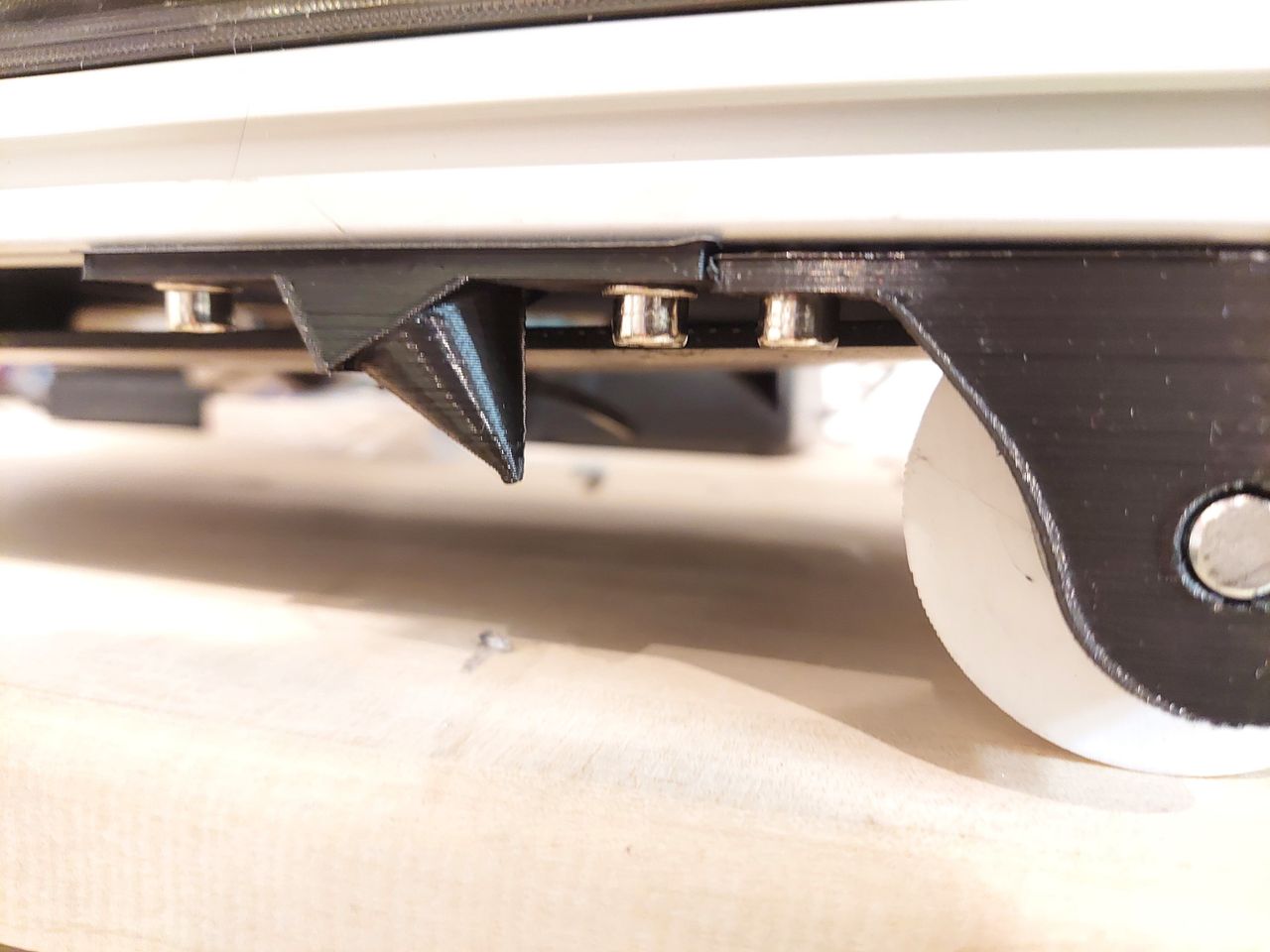
Conveyor Unit: The Gap between belt and Frame will be closed with 3D printed spacer elements which alo improve the sliding of raw material onto the belt. The light barrier is rearranged a little bit to prevent fail detections.
software: The software will give the possibility to change the start / stop time via control panel
13
V3 Frame update
Published 1y. Edited 1yPublished over 1 year ago. Last edit over 1 year ago
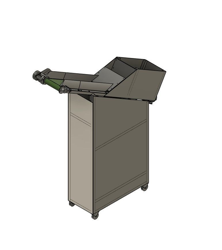
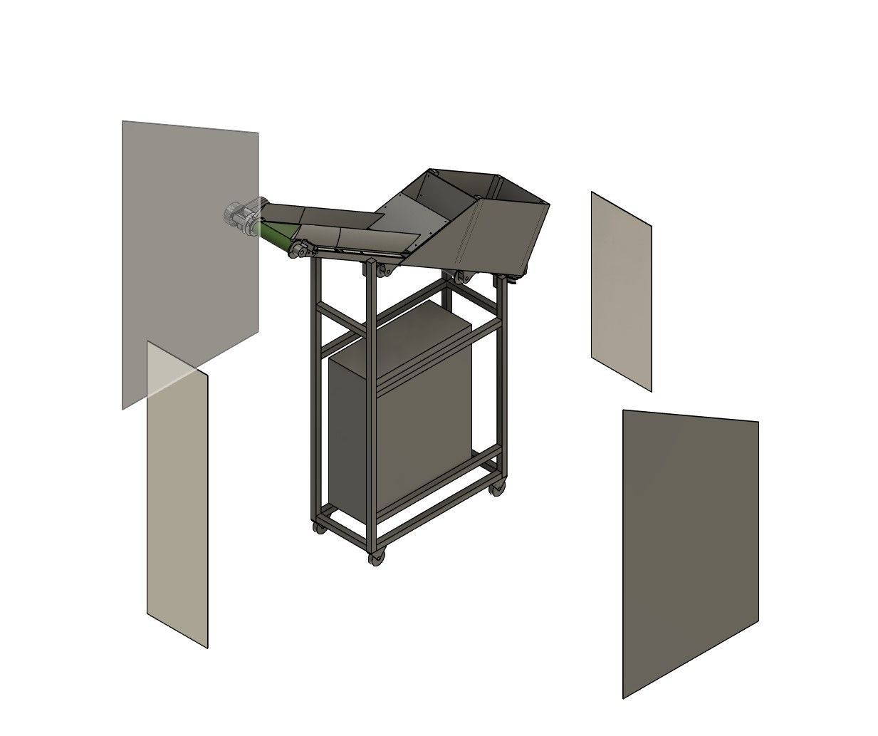
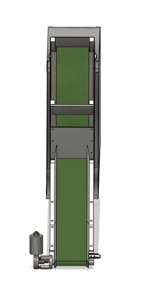
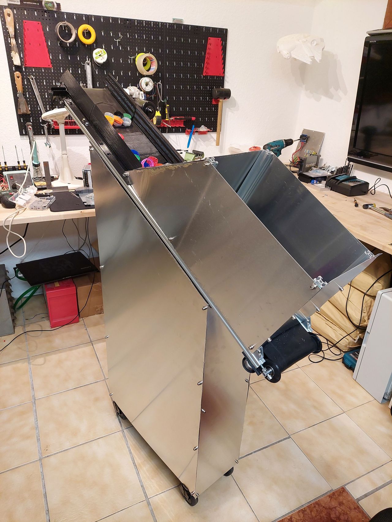
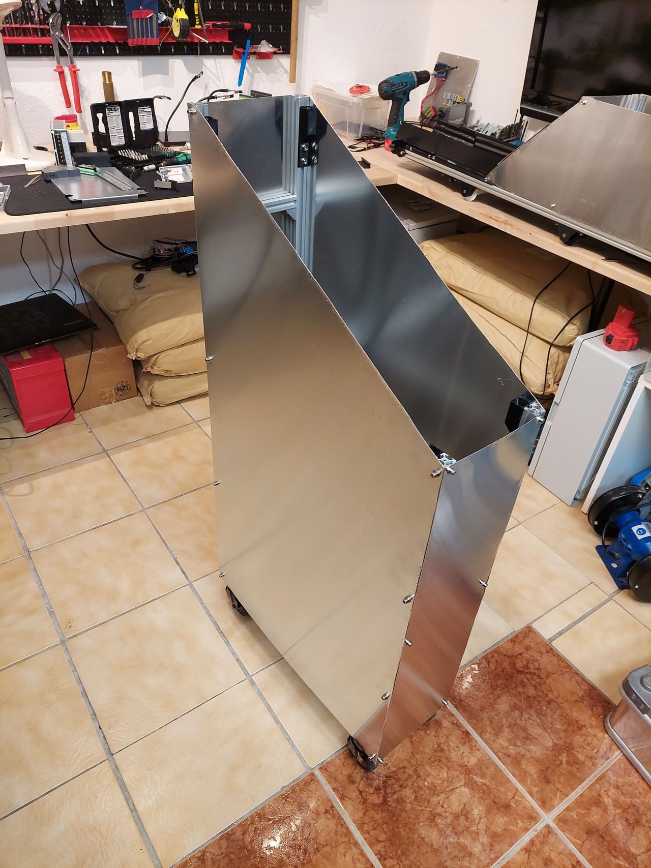
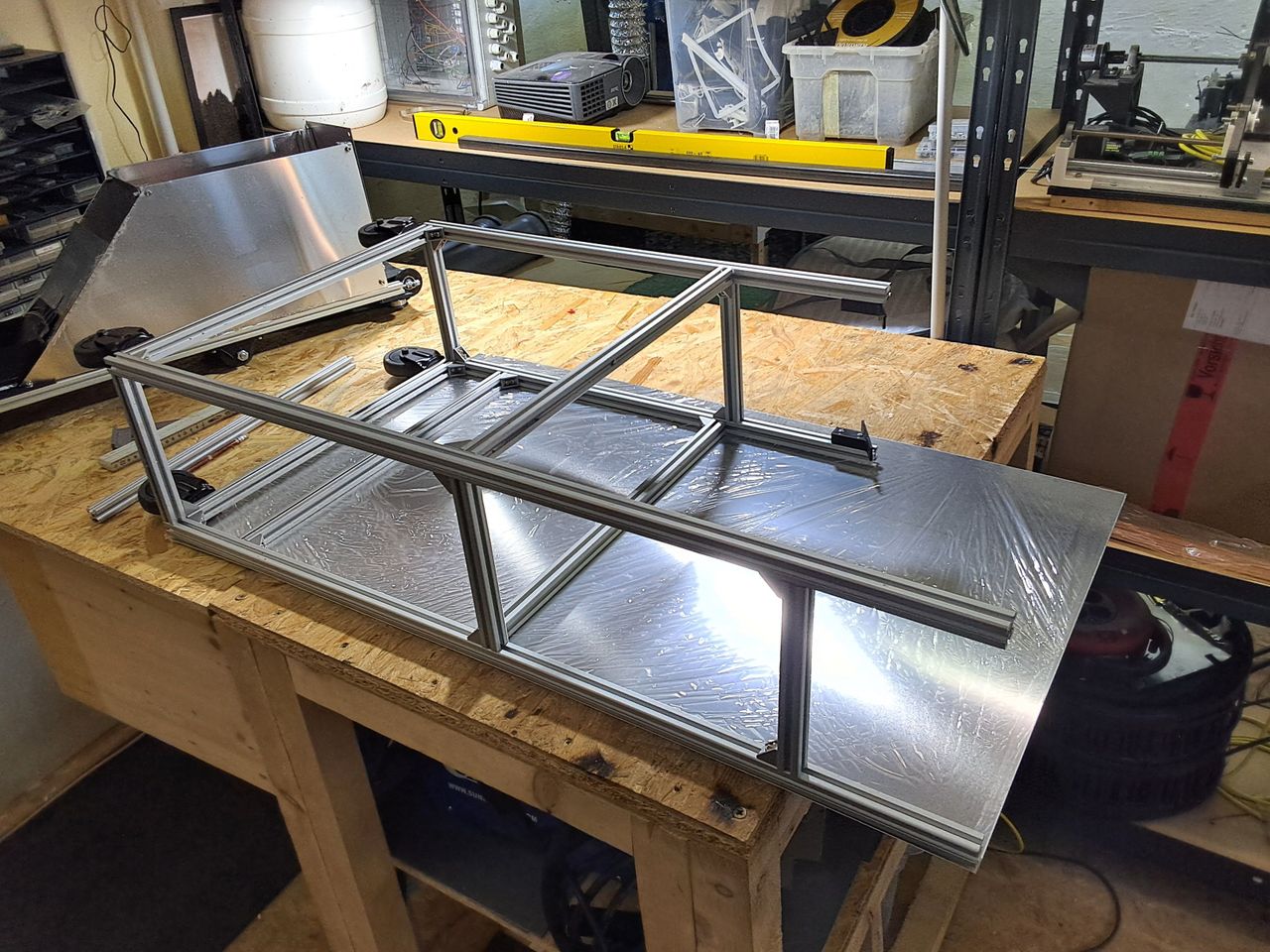
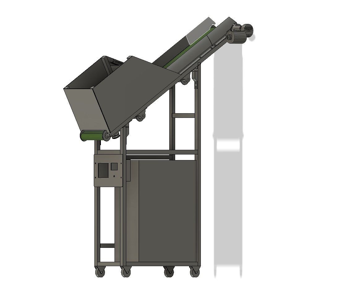
The depth of the frame has been adjusted to fit under the belt without a lateral gap.
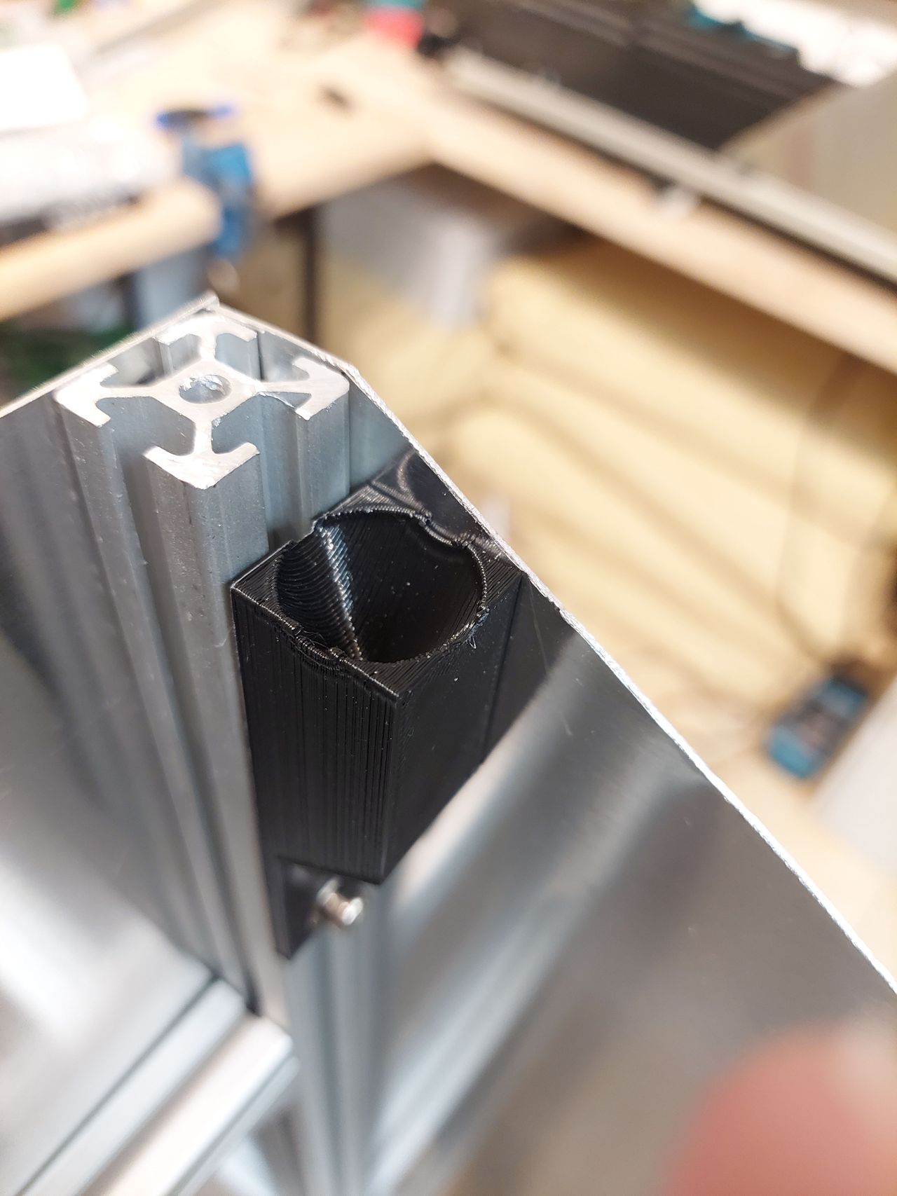
Metal sheets serve as a housing and the conveyour can easily be put on by a cone connector.
14
V3 Conveyor Belt Update
Published 1y. Edited 1yPublished over 1 year ago. Last edit over 1 year ago
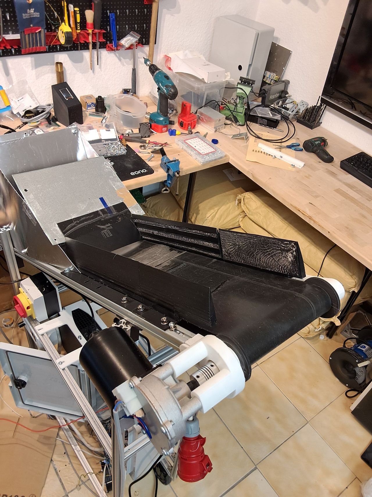
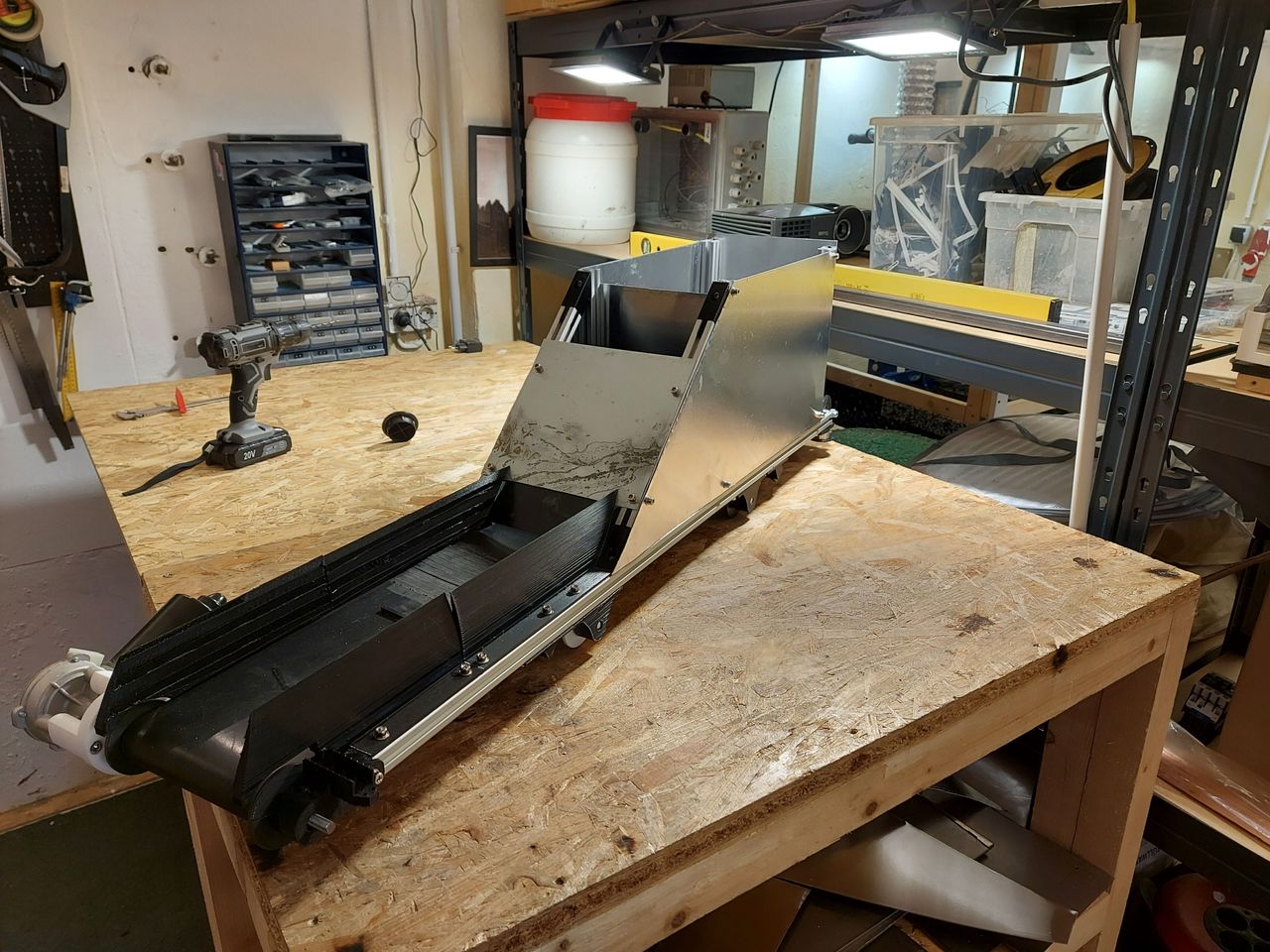
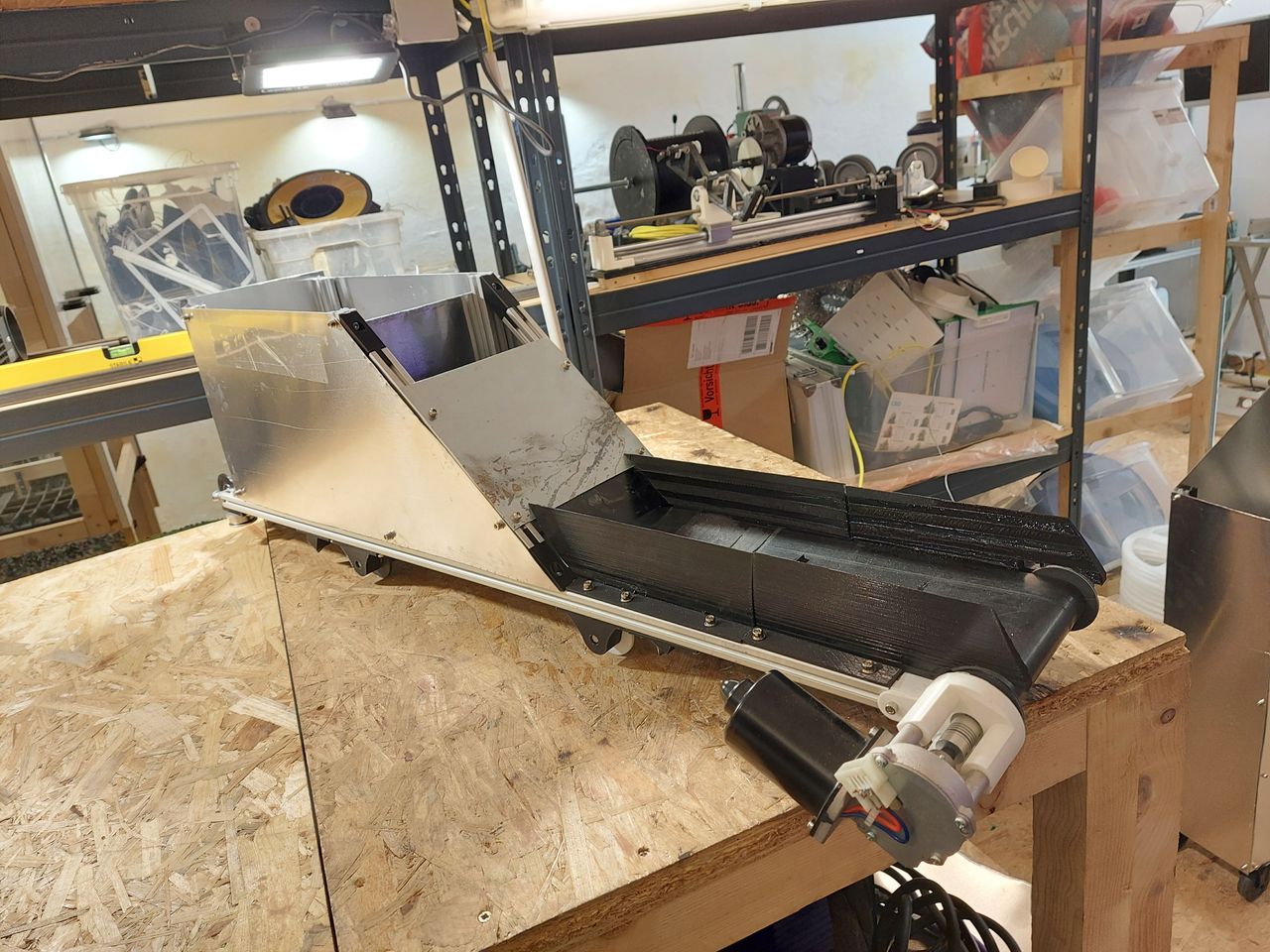
The frame has already been upgraded, let's do the same with the belt unit. The structure of the machine is kind of modular. So the frame, the conveyor belt and the housing are three individual modules that can be modified separately.
The lower side of the conveyor has now cones to fit nicely in it's counterpart on the frame. This makes it quite easy to place the belt on the frame.
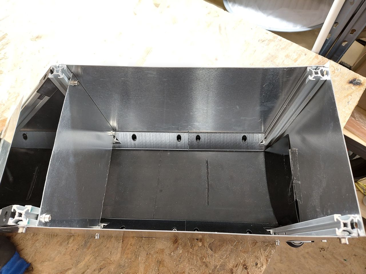
The gap between the rubber belt and the frame is now closed with 3d printed elements which also make the material slide on the belt. No more material stucked under the belt any longer.
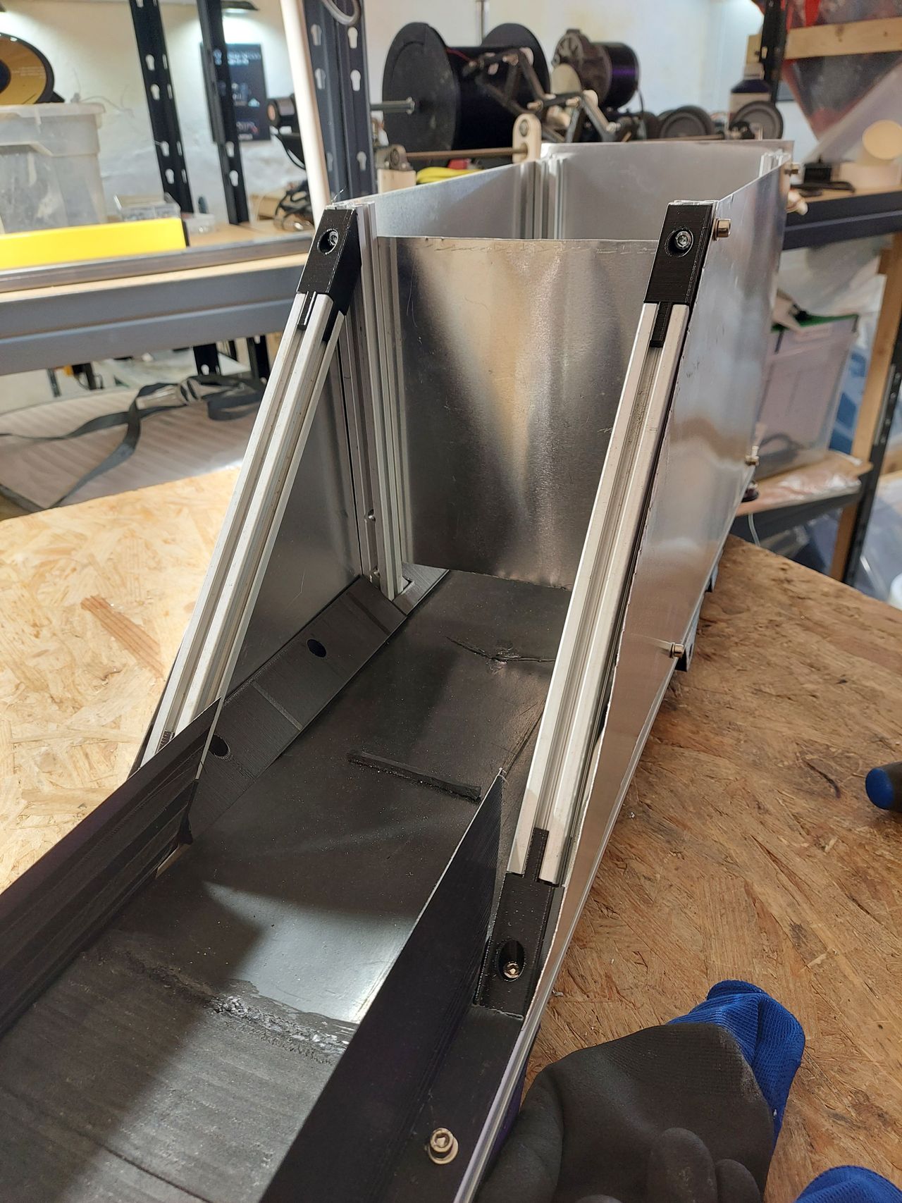
the font of the hopper has slanted aluminium elements which simplifies the assembly of the separartor sheet
15
V3 cabinet update
Published 1y. Edited 1yPublished over 1 year ago. Last edit over 1 year ago
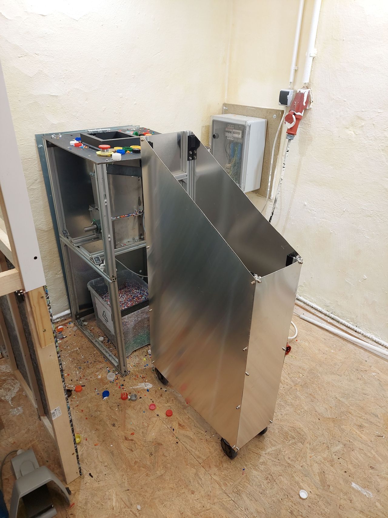
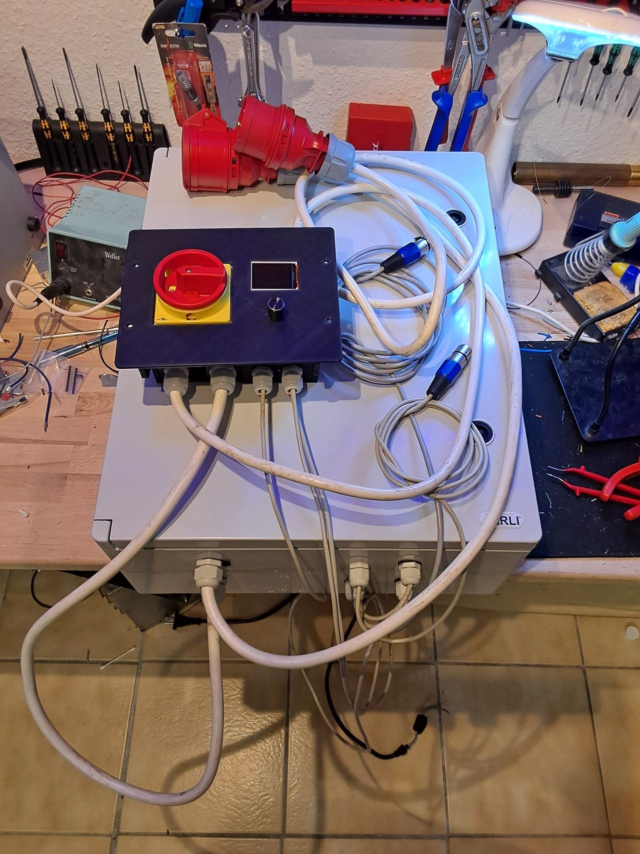
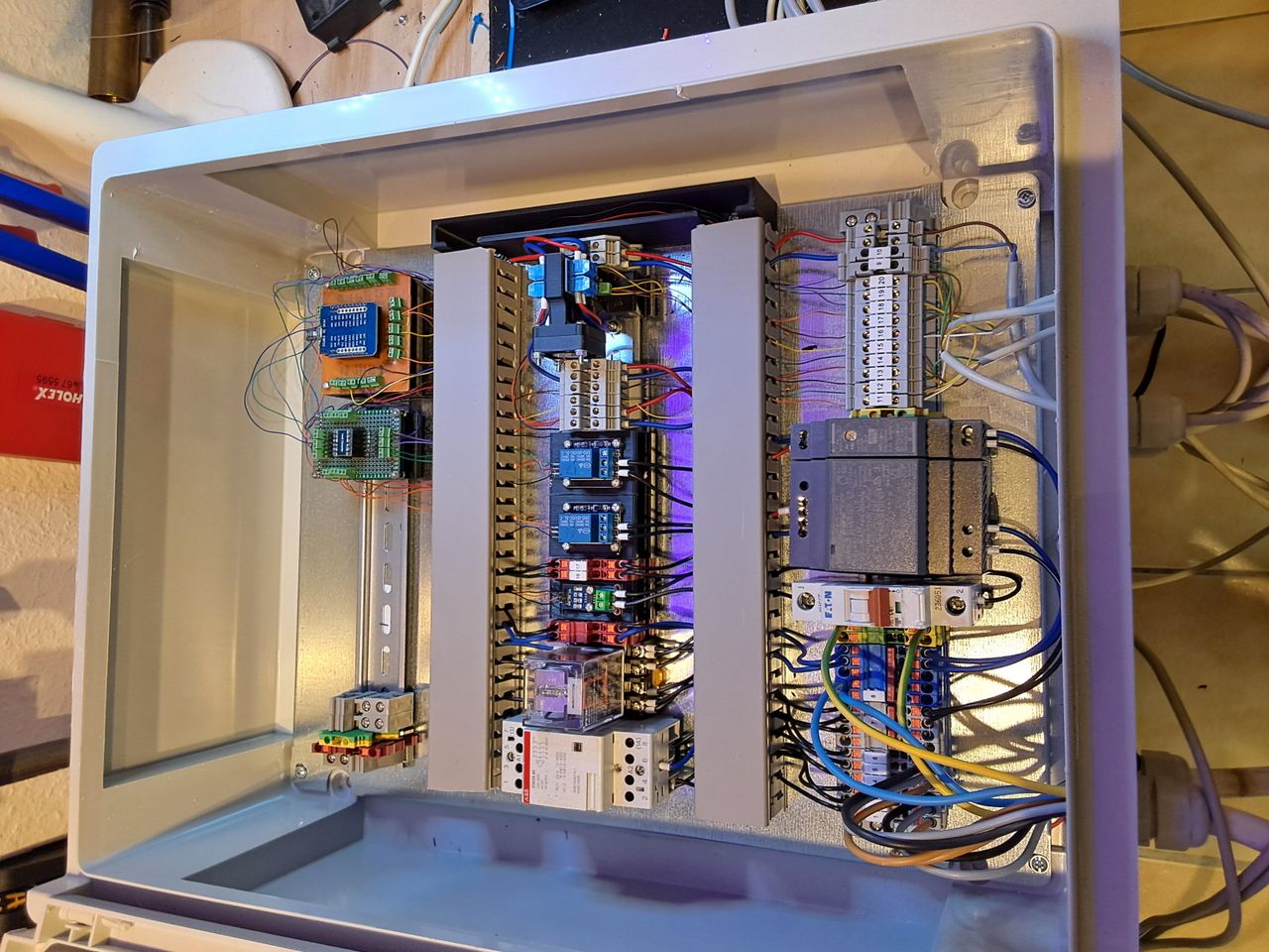
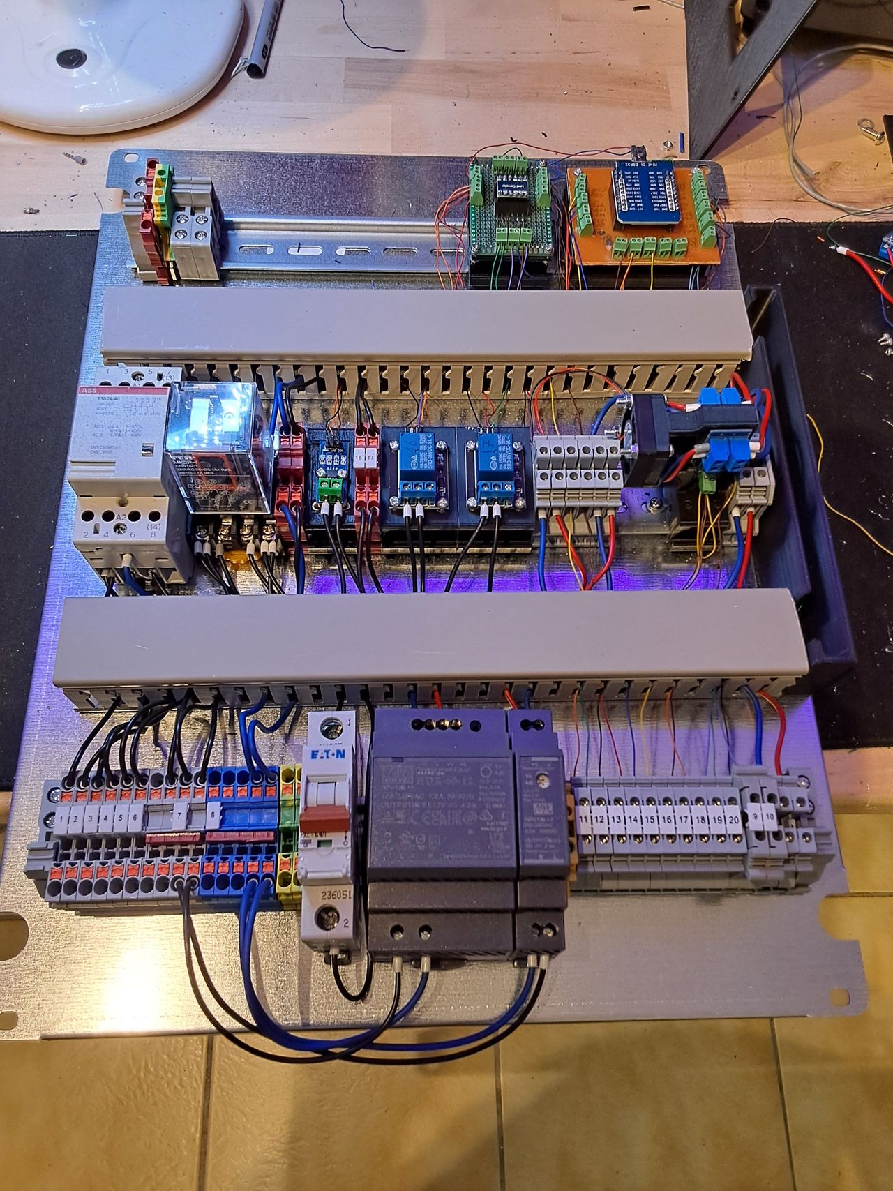
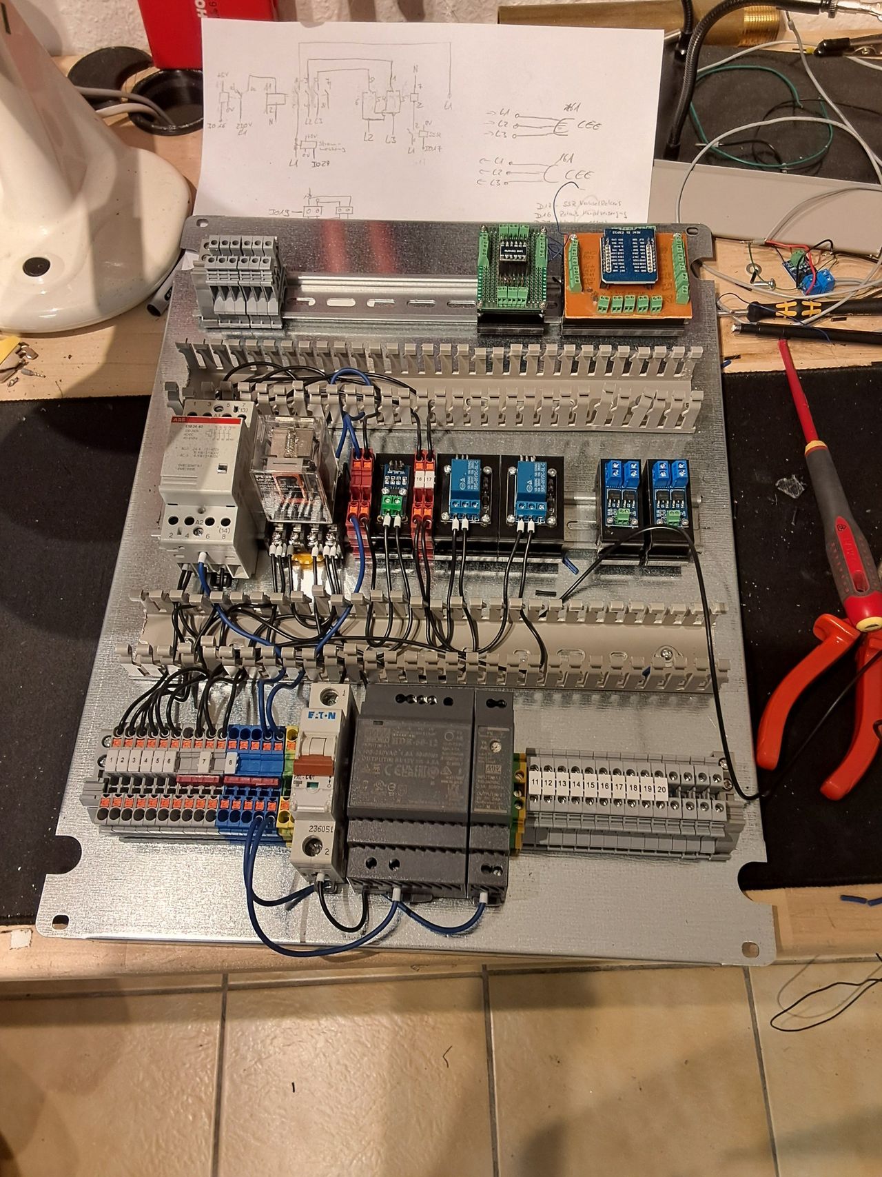
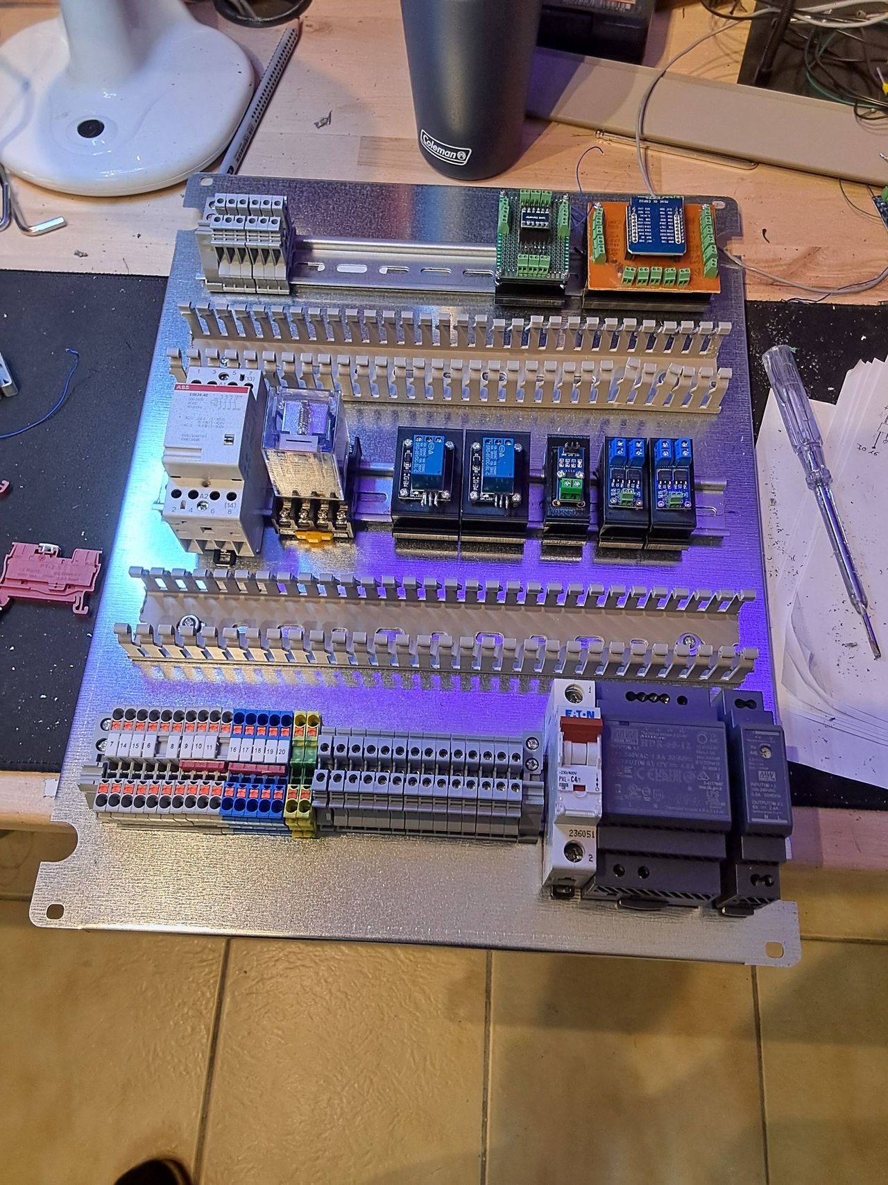
Like the conveyor belt and the frame, the cabinet is now a separate hackable stand alone module. The small cabinet has been replaced by a lager version which allows nicer wiring.
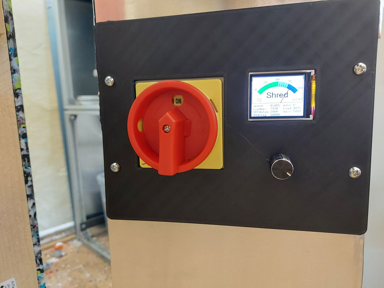
Main switch and display are combined in a front panel at the rear side of the feeder.
Power supply, shredder, beltmotor and lightbarrier are all connected via plugs, no extra wiring needed.
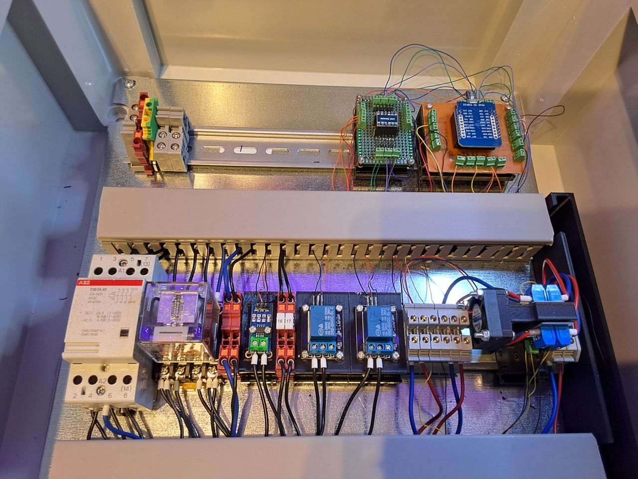
In terms of electonic components a DIN rail power supply is used, the mosfet driver for the motor have a small cooling fan and the relays are equipped with snubbers to prevent electromagnetic interference.
16
v3 software update
Published 1yPublished about 1 year ago
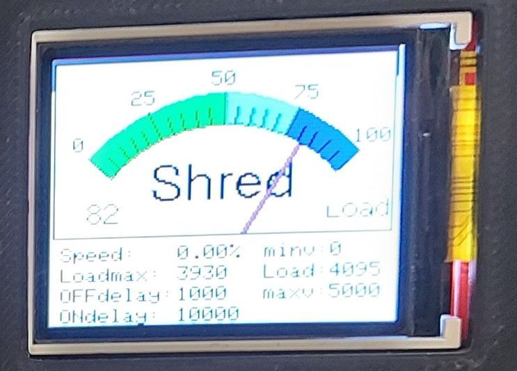
last update for the v3 version is the software.
The biggest changes are the switching times and limit values for the light barrier, the analog display and the automatic return that can be changed via the display
The belt also had the bad feature to start the shredder in reverse mode when powered up. Therefore some also some programm changes were needed
17
Version 3 - final
Published 1y. Edited 1yPublished about 1 year ago. Last edit about 1 year ago
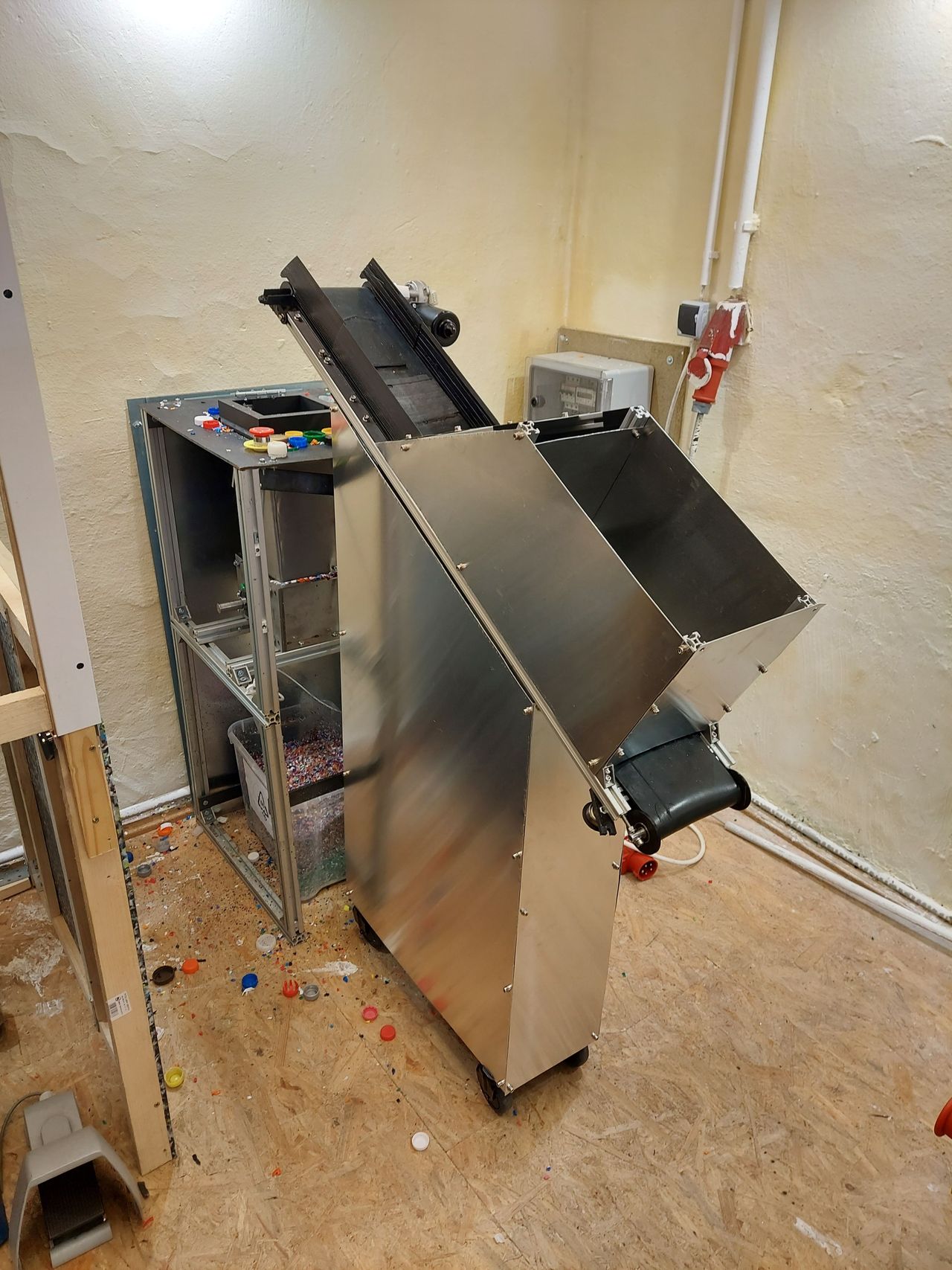
Covered Housing, panel on the rearside, new cabinet, upgraded belt and software. Auto stop via light barrier and shredder overload protection is also working. So, looks like the project is finished.
%20--%3e%3csvg%20version='1.1'%20id='Layer_1'%20xmlns='http://www.w3.org/2000/svg'%20xmlns:xlink='http://www.w3.org/1999/xlink'%20x='0px'%20y='0px'%20viewBox='0%200%2064%2063'%20style='enable-background:new%200%200%2064%2063;'%20xml:space='preserve'%3e%3cstyle%20type='text/css'%3e%20.st0{fill:%2320B7EB;}%20.st1{fill:%23E9475A;}%20.st2{fill:%23FECE4E;}%20%3c/style%3e%3cdesc%3eCreated%20with%20Sketch.%3c/desc%3e%3cg%20id='Page-1'%3e%3cg%20id='OA-Logo-Black-Background'%3e%3cpath%20id='Shape'%20class='st0'%20d='M14.1,30.1c-1.5-0.8-8.6-3.8-14.1-7.8c1.8-3.4,3.1-5.6,5-9.1c2.7,1.1,1.9,0.5,4.6,1.7%20c0.8,0.4,10.1,4.5,13.8,6.2c2.4,1.1,4.7,2.2,7,3.3L43,30.5l8.1,3.9c4,2,7.2,3.5,11.3,5.5c0.5,0.3-3.7,9.4-3.7,9.4%20c-1.7-0.6-3.9-1.8-5.5-2.5c-4.7-2.1-9-3.9-13.7-6c-4-1.8-6.7-2.9-10.8-4.5C25,34.9,17.1,31.6,14.1,30.1z'/%3e%3cpath%20id='Shape_1_'%20class='st1'%20d='M12.1,54.9c-0.8,0.6-1.6,1.2-2.5,1.6c-0.4-0.5-0.9-1-1.3-1.5c-0.3-1.2-2.3-4.9-2.7-6.2%20c-0.1-0.4-0.7-2.2-0.8-2.6c0,0,5-3.4,8.2-5.9c3.2-2.6,6.2-5,9.3-7.5c1.4-1.1,3.9-2.5,5.3-3.5c2.5-1.7,13-9.1,15.6-10.5%20c5.4-3.3,11.1-6.3,16.8-9c1.7,3.5,1.8,3,3.8,6.9c0,0-17.8,13.5-22.7,17.1c-3.8,2.8-7.5,5.7-11.3,8.5c-1.7,1.3-3.5,2.4-5.2,3.7'/%3e%3cpath%20id='Shape_2_'%20class='st2'%20d='M20.8,2.9l-0.2-0.8C25,0,31.2-0.3,31.4,0.2c0.4,1.1,0.9,2.2,1.2,3.4c1.4,4.4,2.7,8.7,4,13.1%20c0.4,1.4,2.8,10,2.9,10.5c0.5,2.8,1.2,5.6,1.6,8.4c0.8,4.7,1.4,8.6,2.3,13.3c0.6,3.1,1.3,6.3,2.3,11.3c0,0-5.8,1.4-7.5,1.8%20c-0.8,0.2-1.5,0.4-2.4,0.6c-0.3-1.1-0.2-1.2-0.5-2.1c-0.9-3.7-1.8-7.3-2.6-11c-1.5-6.4-3-12.9-4.4-19.3%20c-1.2-5.4-2.6-10.7-4.4-15.9c-1-3.1-1.8-6.3-2.7-9.5C21.1,3.8,21,3.8,20.8,2.9z'/%3e%3c/g%3e%3c/g%3e%3c/svg%3e)