
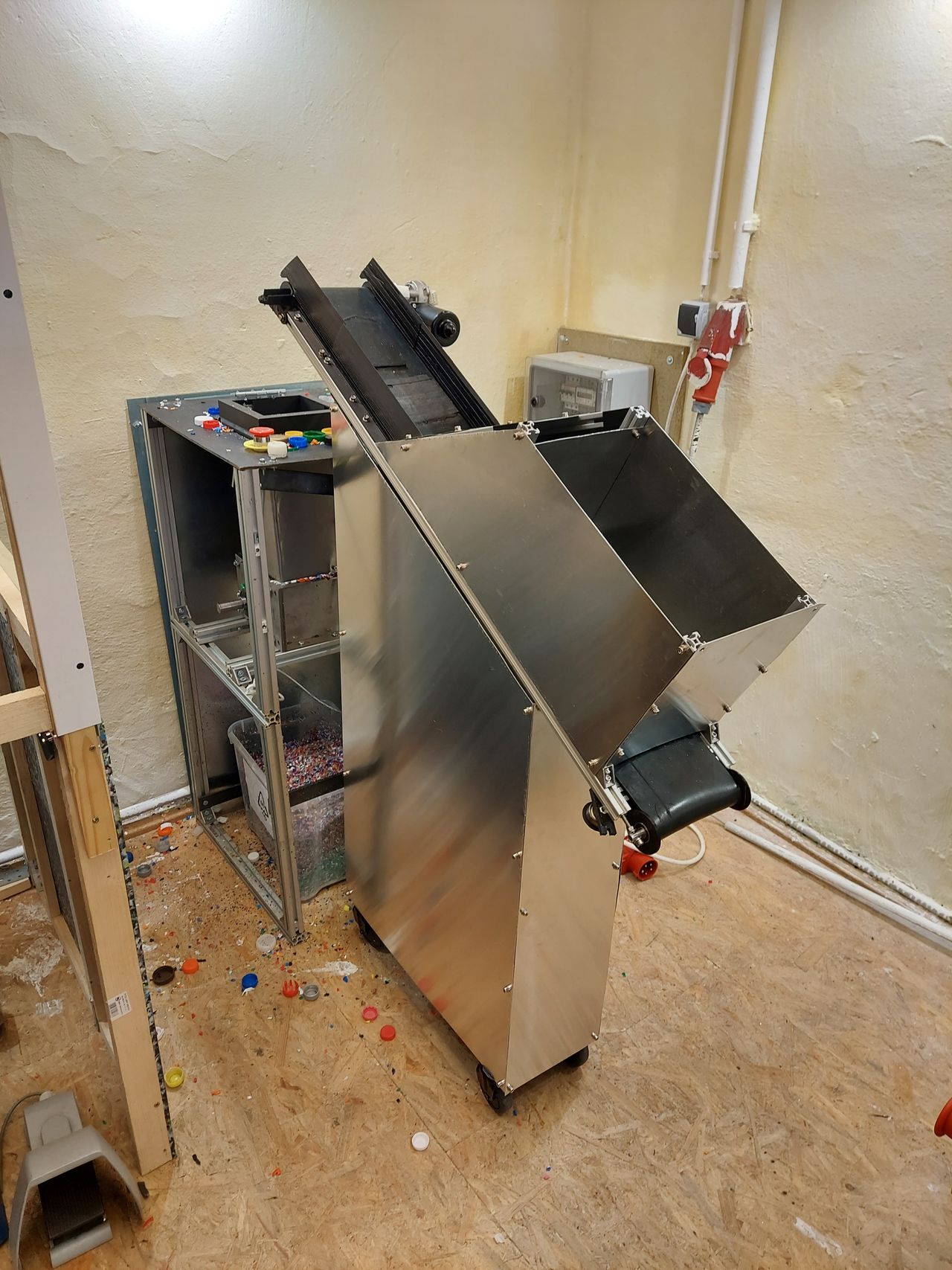
Automatic belt feeder for the shredder
The machine automatically feeds material into the shredder. Especially with low throughput shredders, it makes the recycling process less time-consuming and more cost-effective. You no longer have to stand in front of the shredder for hours. The device adjusts its feed rate to the capacity of the shredder and can clear the blades in the event of a blockage by means of an automatic right-left rotation sequence. The machine consists of three main components: frame, electronics, and conveyor belt, which can be hacked independently of each other.shredder
%20--%3e%3csvg%20version='1.1'%20id='Calque_1'%20xmlns='http://www.w3.org/2000/svg'%20xmlns:xlink='http://www.w3.org/1999/xlink'%20x='0px'%20y='0px'%20viewBox='0%200%2027.2%2027.8'%20style='enable-background:new%200%200%2027.2%2027.8;'%20xml:space='preserve'%3e%3ctitle%3eicon%20redirect%20new%3c/title%3e%3cg%3e%3cpath%20d='M27.2,26.5c-0.1-5-0.3-10-0.4-15c0-0.7-0.6-1.2-1.2-1.2s-1.2,0.6-1.2,1.2c0.1,4.6,0.3,9.1,0.4,13.7%20c-3.9-0.2-7.7-0.6-11.6-0.4c-3.3,0.2-6.7,0.5-10,0.4C2.8,19.5,2.7,13.7,2.5,8c2.9-0.1,5.8-0.8,8.6-0.7c1.6,0.1,1.6-2.4,0-2.5%20C7.8,4.6,4.5,5.7,1.2,5.5c-0.6,0-1,0.3-1.1,0.7C0,6.3,0,6.4,0,6.6c0,0,0,0.1,0,0.1c0,0,0,0,0,0.1c0.2,6.6,0.4,13.2,0.5,19.7%20c0,0.6,0.4,1.3,1.2,1.4c3.8,0.1,7.5-0.2,11.3-0.4c4.4-0.3,8.6,0.2,12.9,0.4c0.6,0,1-0.3,1.1-0.7C27.1,26.9,27.2,26.7,27.2,26.5z'/%3e%3cpath%20d='M12,12.6c-0.2,0.7,0.2,1.4,0.9,1.5c0.7,0.2,1.4-0.2,1.5-0.9v0c0.6-2.2,1.4-4.5,3.1-6c1.3-1.2,3-1.9,4.7-2.7%20c-0.4,1.3-0.8,2.6-1.4,3.8c-0.6,1.5,1.8,2.1,2.4,0.7c0.8-1.9,1.5-3.9,2-5.9c0-0.1,0-0.2,0-0.3c0.3-0.6,0.1-1.5-0.7-1.8%20C22.3,0.4,20,0,17.7,0c-0.7,0-1.2,0.6-1.2,1.2s0.6,1.2,1.2,1.2c0.9,0,1.7,0.1,2.6,0.2c-1.7,0.8-3.4,1.7-4.8,3%20C13.6,7.6,12.7,10.1,12,12.6z'/%3e%3c/g%3e%3c/svg%3e)
More Information

%20--%3e%3csvg%20version='1.1'%20id='Layer_1'%20xmlns='http://www.w3.org/2000/svg'%20xmlns:xlink='http://www.w3.org/1999/xlink'%20x='0px'%20y='0px'%20viewBox='0%200%2064%2063'%20style='enable-background:new%200%200%2064%2063;'%20xml:space='preserve'%3e%3cstyle%20type='text/css'%3e%20.st0{fill:%23231F20;}%20%3c/style%3e%3cdesc%3eCreated%20with%20Sketch.%3c/desc%3e%3cg%20id='Page-1'%3e%3cg%20id='OA-Logo-Black-Background'%3e%3cpath%20id='Shape'%20class='st0'%20d='M14.1,30.1c-1.5-0.8-8.6-3.8-14.1-7.8c1.8-3.4,3.1-5.6,5-9.1c2.7,1.1,1.9,0.5,4.6,1.7%20c0.8,0.4,10.1,4.5,13.8,6.2c2.4,1.1,4.7,2.2,7,3.3L43,30.5l8.1,3.9c4,2,7.2,3.5,11.3,5.5c0.5,0.3-3.7,9.4-3.7,9.4%20c-1.7-0.6-3.9-1.8-5.5-2.5c-4.7-2.1-9-3.9-13.7-6c-4-1.8-6.7-2.9-10.8-4.5C25,34.9,17.1,31.6,14.1,30.1z'/%3e%3cpath%20id='Shape_1_'%20class='st0'%20d='M12.1,54.9c-0.8,0.6-1.6,1.2-2.5,1.6c-0.4-0.5-0.9-1-1.3-1.5c-0.3-1.2-2.3-4.9-2.7-6.2%20c-0.1-0.4-0.7-2.2-0.8-2.6c0,0,5-3.4,8.2-5.9c3.2-2.6,6.2-5,9.3-7.5c1.4-1.1,3.9-2.5,5.3-3.5c2.5-1.7,13-9.1,15.6-10.5%20c5.4-3.3,11.1-6.3,16.8-9c1.7,3.5,1.8,3,3.8,6.9c0,0-17.8,13.5-22.7,17.1c-3.8,2.8-7.5,5.7-11.3,8.5c-1.7,1.3-3.5,2.4-5.2,3.7'/%3e%3cpath%20id='Shape_2_'%20class='st0'%20d='M20.8,2.9l-0.2-0.8C25,0,31.2-0.3,31.4,0.2c0.4,1.1,0.9,2.2,1.2,3.4c1.4,4.4,2.7,8.7,4,13.1%20c0.4,1.4,2.8,10,2.9,10.5c0.5,2.8,1.2,5.6,1.6,8.4c0.8,4.7,1.4,8.6,2.3,13.3c0.6,3.1,1.3,6.3,2.3,11.3c0,0-5.8,1.4-7.5,1.8%20c-0.8,0.2-1.5,0.4-2.4,0.6c-0.3-1.1-0.2-1.2-0.5-2.1c-0.9-3.7-1.8-7.3-2.6-11c-1.5-6.4-3-12.9-4.4-19.3%20c-1.2-5.4-2.6-10.7-4.4-15.9c-1-3.1-1.8-6.3-2.7-9.5C21.1,3.8,21,3.8,20.8,2.9z'/%3e%3c/g%3e%3c/g%3e%3c/svg%3e)


1
Frame
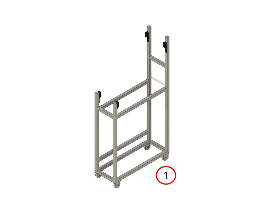
We made the frame from extruded aluminum profiles. Theoretically, you could also use wood, plastic, or other metals. However, we found aluminum to be the easiest solution in terms of assembly and length adjustment.
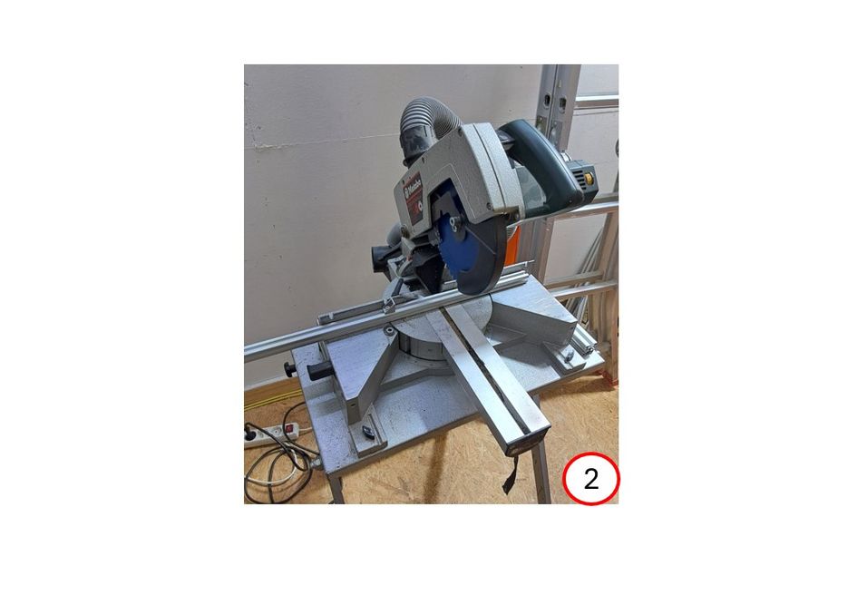
A) Cut the material to size
Once you have the dimensions from the CAD file (1), you can now cut all the struts to the required length (2).
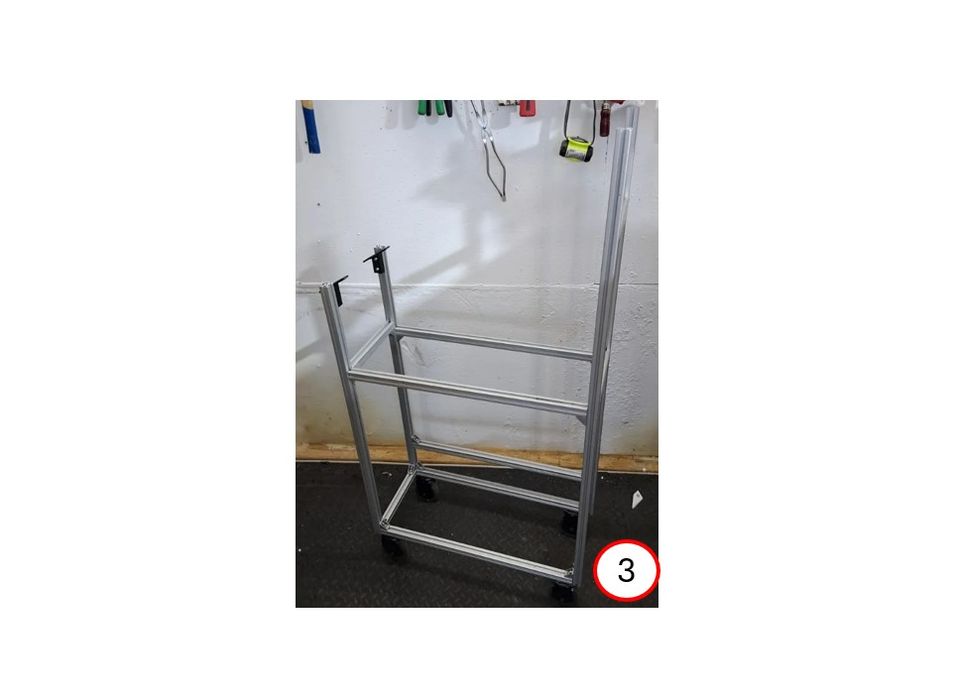
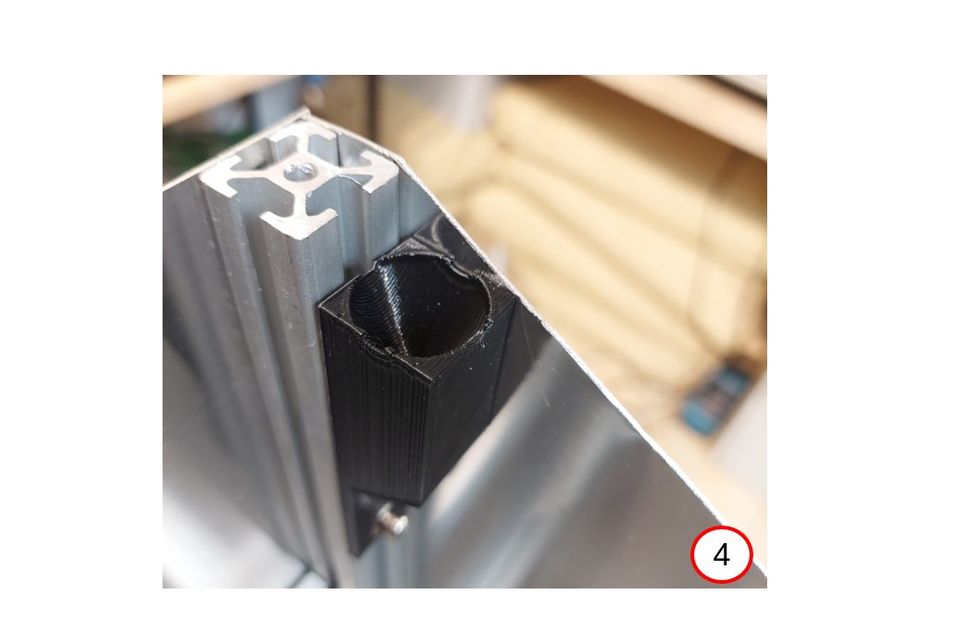
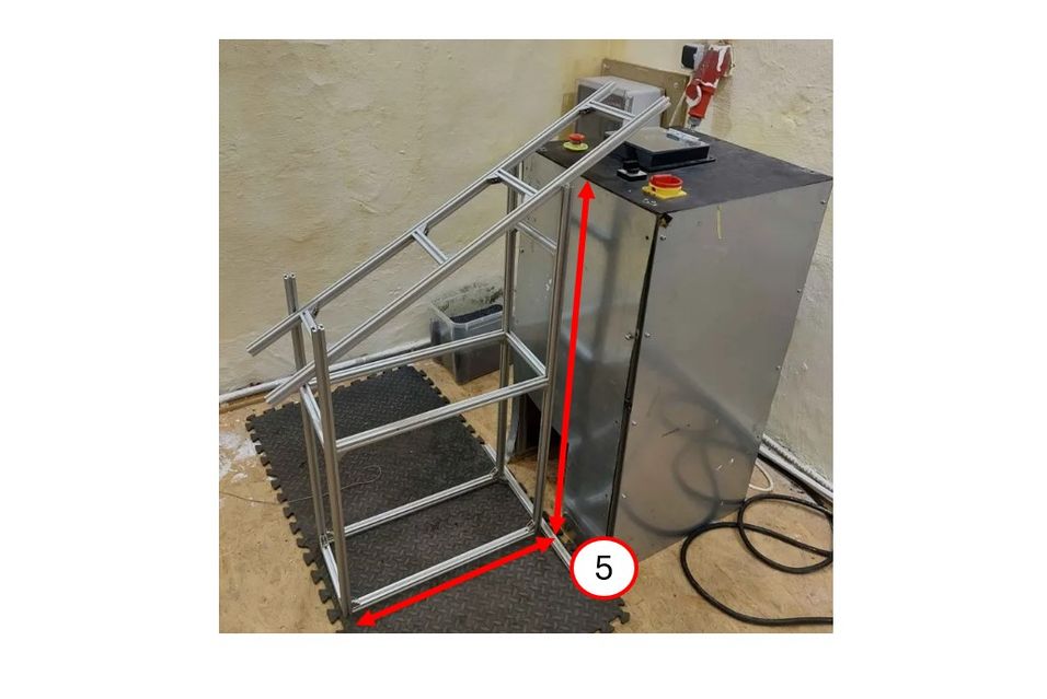
B) Assemble the frame
Now you have all the frame parts and can assemble them (3). If you want to be sure about the dimensions, now is a good time to place the frame in front of the shredder to check again (5). Attach the plastic brackets to the frame, which will later be used to attach the conveyor belt (4).
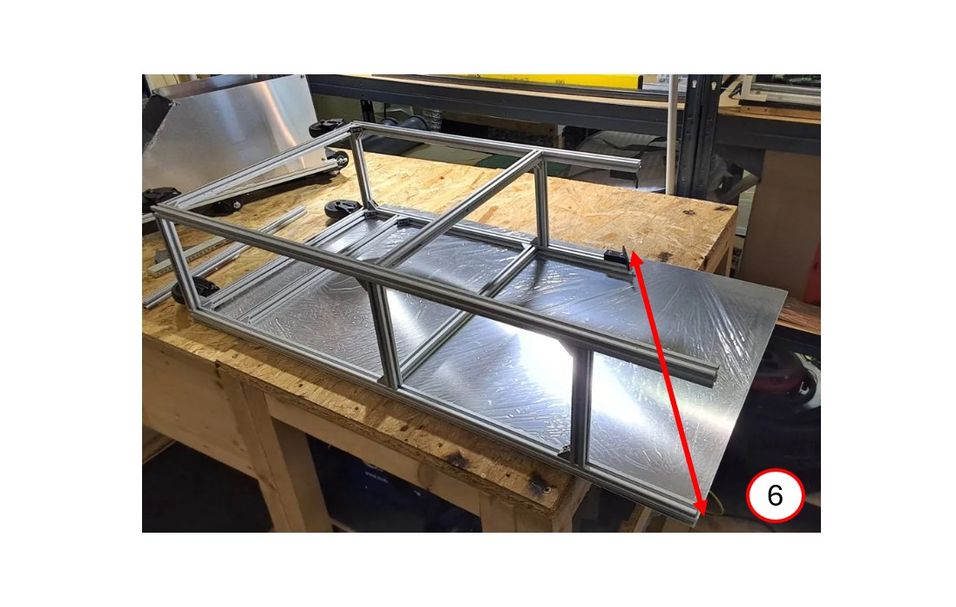
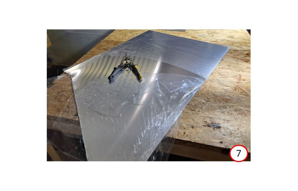
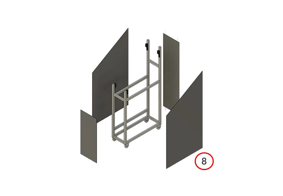
C) Cut sheets and assemble the housing
We used 0.5 mm thick sheets for the housing, as these are easy to cut with tin snips (6+7). Drill mounting holes in the sheets and fasten them with T-nuts and screws (8).
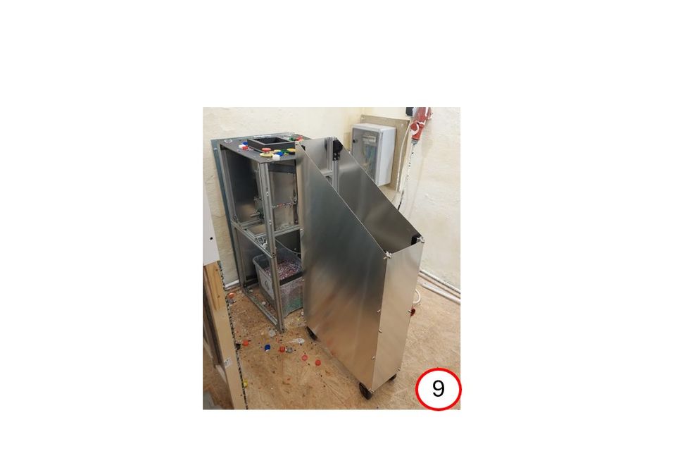
Voilà, your frame is ready (9).
2
Electronics
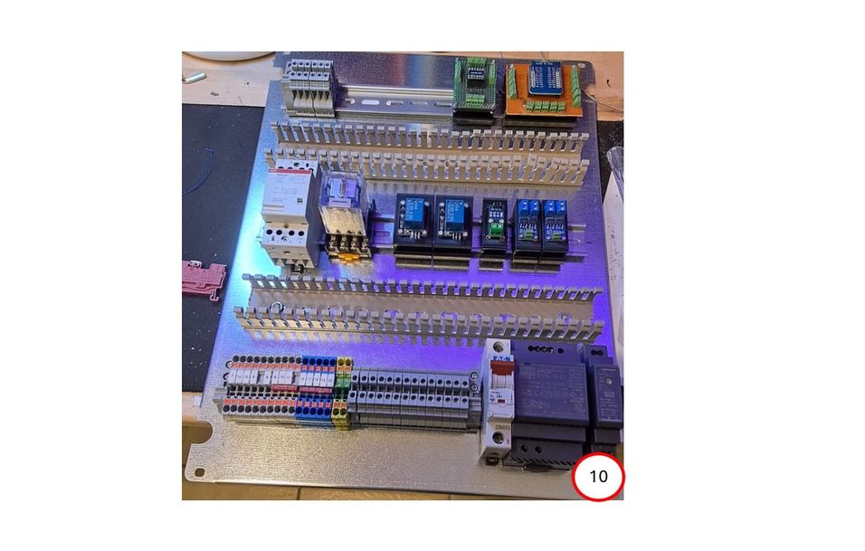
A) Control cabinet
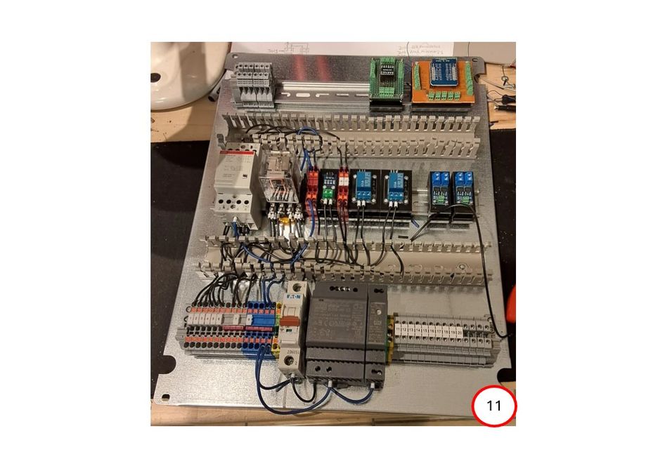
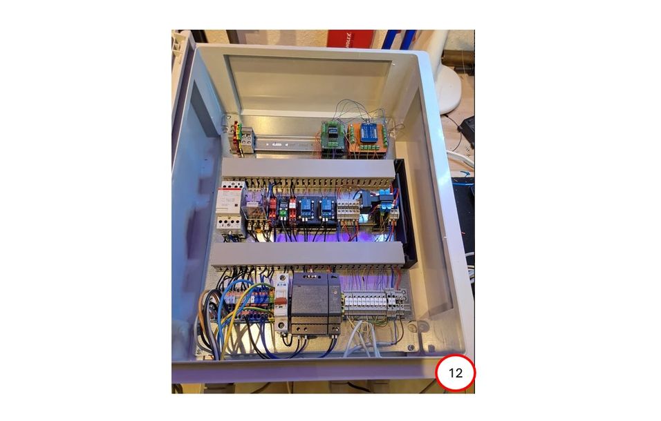
We used a 400 x 600 mm control cabinet with a mounting plate. By removing the plate, DIN rails and cable ducts can be easily installed (10). You can then attach all electrical connections and components to the rails (11). Note that there are some 3D-printed brackets for small circuit boards such as relays, PWM controllers, level converters, and microcontrollers. Once everything is assembled and wired, the plate can be reinserted into the cabinet. (12)
B) Add cables and connectors
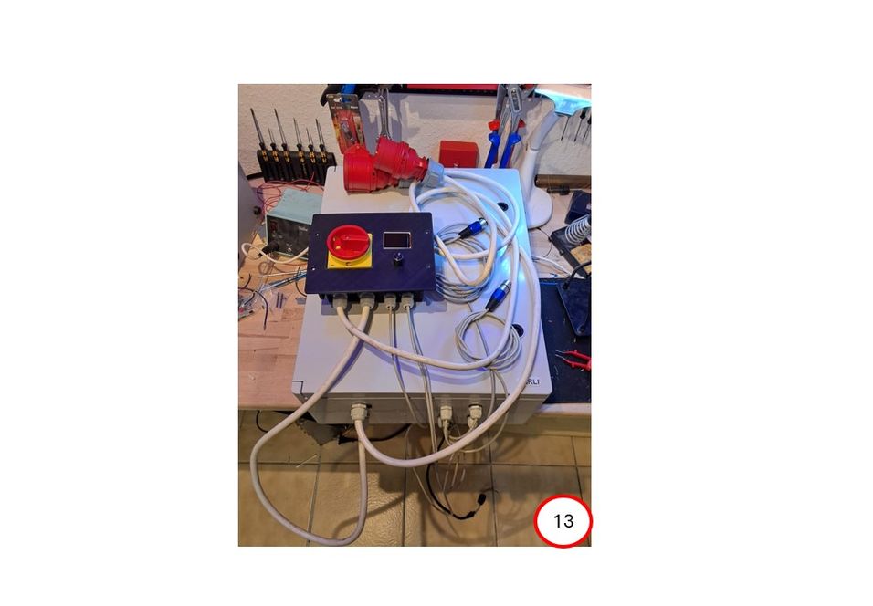
Then add all external cables and connectors. Two connectors for the power supply and the shredder connection, one for the conveyor motor and one for the conveyor light barrier. (13)
C) Connection to the frame
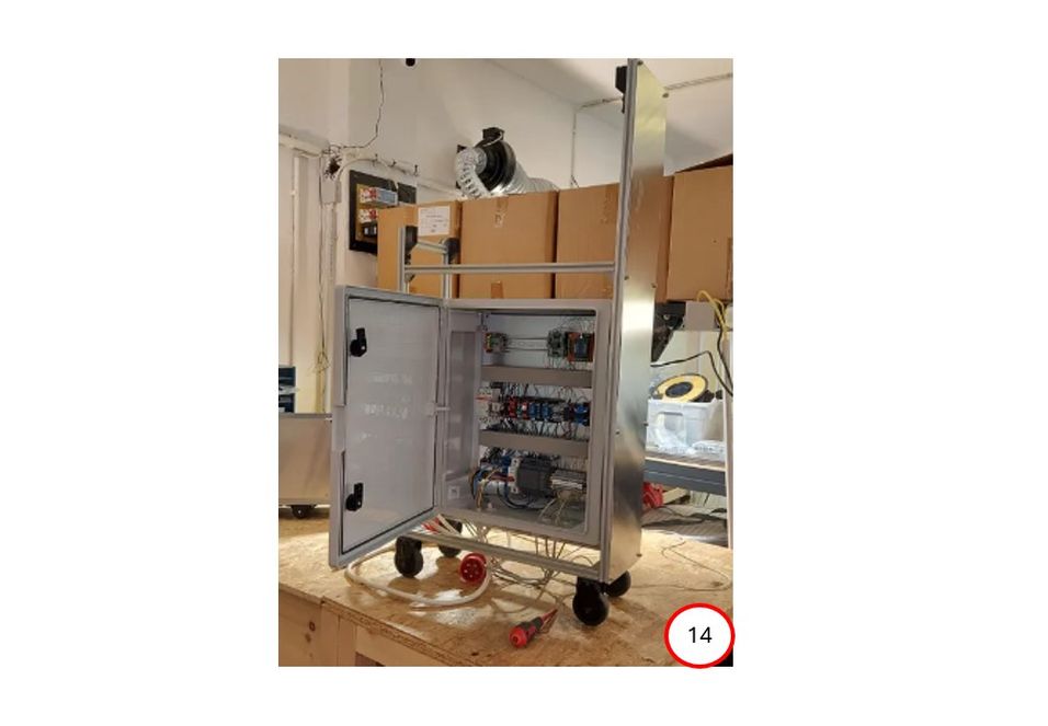
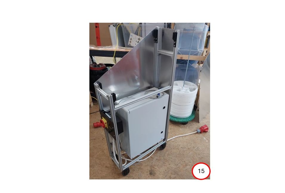
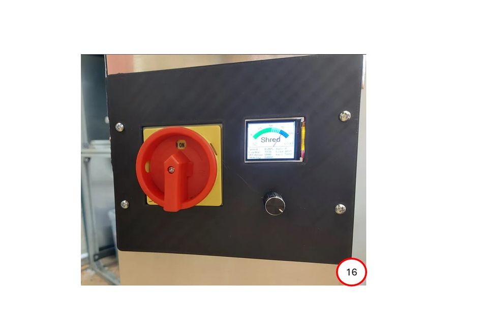
When the entire unit is ready, the cabinet and control unit can be mounted on the frame. (14+15+16)
3
Conveyor
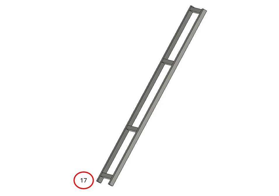
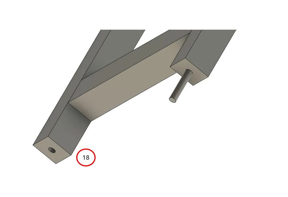
A) Prepare the base frame
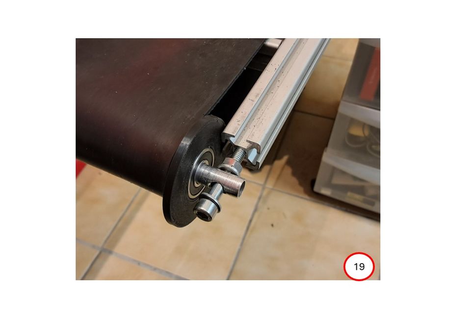
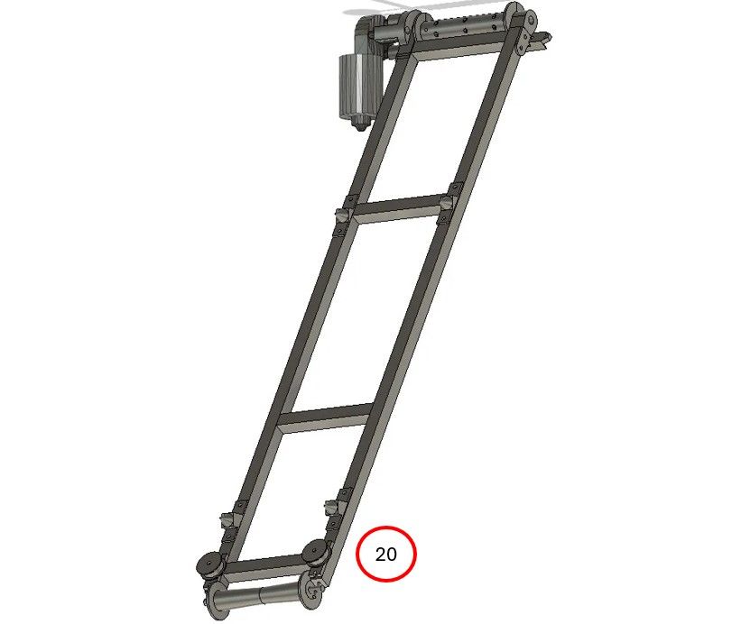
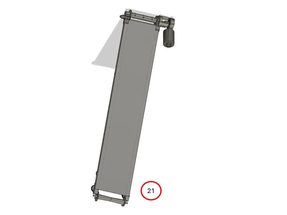
Assemble the metal struts to form a frame (17). Cut two threads into the back of the profiles; the rollers will be attached there later (18). Add the drive roller with motor, the rear roller, the side guide, and the connecting cone (19+20), and finally the base plate. (21)
B) Prepare the belt
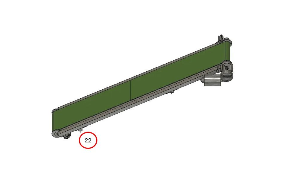
We use a 3000 mm x 150 mm x 3 mm rubber strip with fabric insert. Place the strip around the frame to measure the required length. Then add 50 mm on each side for the adhesive surface. Remove 1.5 mm of material height in this area, then apply the tire adhesive and press both sides together. Once the adhesive has dried, pull the strap over the base frame. (22)
C) Assemble the funnel and side barrier
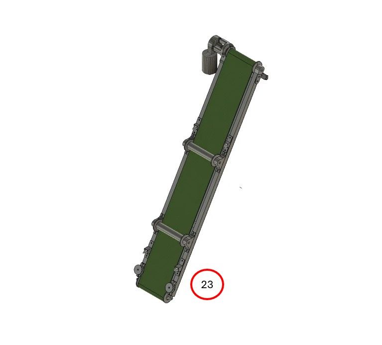
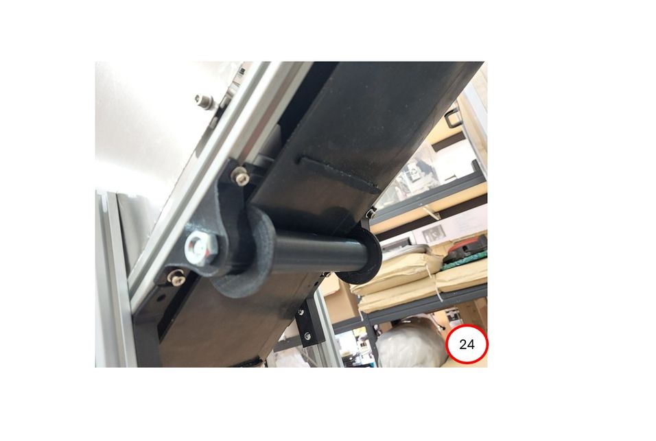
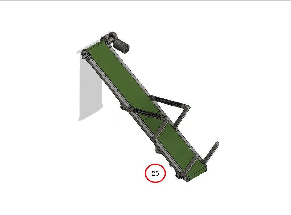
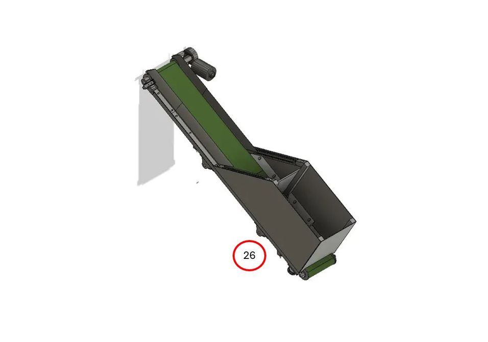
Turn the device over, add the lower rollers and bearings. (23+24) Turn it over again and assemble the profiles for the funnel. (25) Now you can add the boundary elements and cover plates as well as the light barrier. (26)
4
Marriage
A) CONNECTING THE CONVEYOR BELT AND FRAME
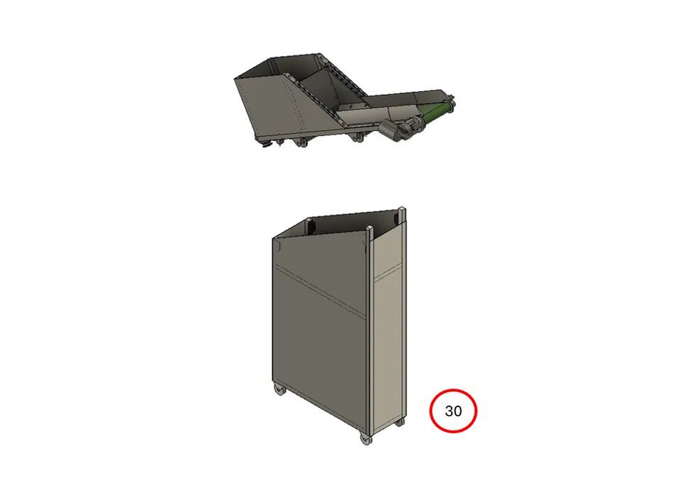
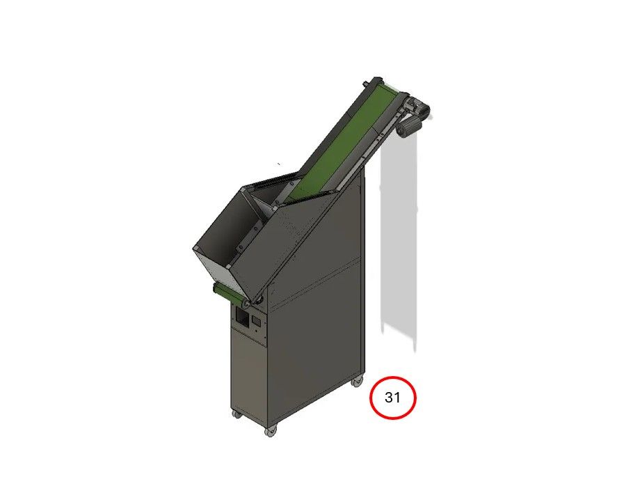
To connect the conveyor belt and frame, ensure that the cones on the underside of the conveyor belt are in the correct position so that they fit into their counterparts on the frame. Then connect the motor and the light barrier plug to the frame electronics. (30) Both parts are now ready to be snapped into place.
Lift the conveyor belt over the frame and lower it slowly until both cone parts are resting on top of each other. (31)
B) TEST RUN
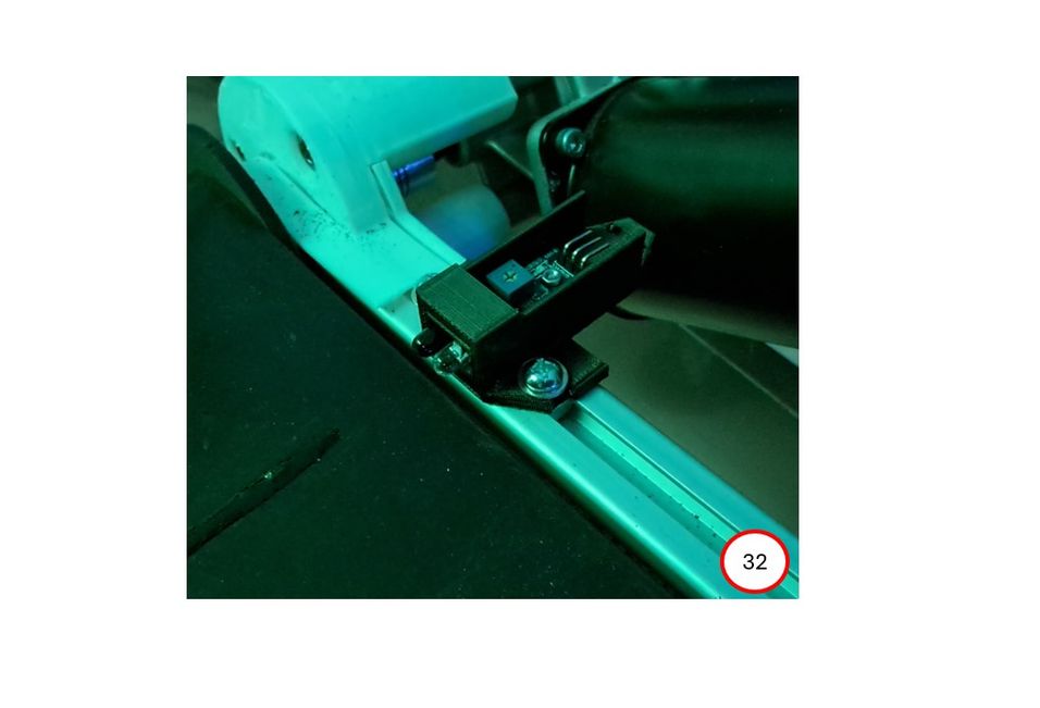
The device is now ready for a test run. Connect the shredder and the power supply. Set the main switch to ON and turn the encoder knob clockwise until the speed reaches 70%. The belt should now rotate evenly. Next, test and adjust the light barrier. (32) When triggered, the belt should stop for a few seconds. Finally, test the jam protection. Throw plastic into the shredder to cause a jam. Ideally, the shredder and belt motors should stop immediately. The shredder should make a few backward revolutions
%20--%3e%3csvg%20version='1.1'%20id='Layer_1'%20xmlns='http://www.w3.org/2000/svg'%20xmlns:xlink='http://www.w3.org/1999/xlink'%20x='0px'%20y='0px'%20viewBox='0%200%2064%2063'%20style='enable-background:new%200%200%2064%2063;'%20xml:space='preserve'%3e%3cstyle%20type='text/css'%3e%20.st0{fill:%2320B7EB;}%20.st1{fill:%23E9475A;}%20.st2{fill:%23FECE4E;}%20%3c/style%3e%3cdesc%3eCreated%20with%20Sketch.%3c/desc%3e%3cg%20id='Page-1'%3e%3cg%20id='OA-Logo-Black-Background'%3e%3cpath%20id='Shape'%20class='st0'%20d='M14.1,30.1c-1.5-0.8-8.6-3.8-14.1-7.8c1.8-3.4,3.1-5.6,5-9.1c2.7,1.1,1.9,0.5,4.6,1.7%20c0.8,0.4,10.1,4.5,13.8,6.2c2.4,1.1,4.7,2.2,7,3.3L43,30.5l8.1,3.9c4,2,7.2,3.5,11.3,5.5c0.5,0.3-3.7,9.4-3.7,9.4%20c-1.7-0.6-3.9-1.8-5.5-2.5c-4.7-2.1-9-3.9-13.7-6c-4-1.8-6.7-2.9-10.8-4.5C25,34.9,17.1,31.6,14.1,30.1z'/%3e%3cpath%20id='Shape_1_'%20class='st1'%20d='M12.1,54.9c-0.8,0.6-1.6,1.2-2.5,1.6c-0.4-0.5-0.9-1-1.3-1.5c-0.3-1.2-2.3-4.9-2.7-6.2%20c-0.1-0.4-0.7-2.2-0.8-2.6c0,0,5-3.4,8.2-5.9c3.2-2.6,6.2-5,9.3-7.5c1.4-1.1,3.9-2.5,5.3-3.5c2.5-1.7,13-9.1,15.6-10.5%20c5.4-3.3,11.1-6.3,16.8-9c1.7,3.5,1.8,3,3.8,6.9c0,0-17.8,13.5-22.7,17.1c-3.8,2.8-7.5,5.7-11.3,8.5c-1.7,1.3-3.5,2.4-5.2,3.7'/%3e%3cpath%20id='Shape_2_'%20class='st2'%20d='M20.8,2.9l-0.2-0.8C25,0,31.2-0.3,31.4,0.2c0.4,1.1,0.9,2.2,1.2,3.4c1.4,4.4,2.7,8.7,4,13.1%20c0.4,1.4,2.8,10,2.9,10.5c0.5,2.8,1.2,5.6,1.6,8.4c0.8,4.7,1.4,8.6,2.3,13.3c0.6,3.1,1.3,6.3,2.3,11.3c0,0-5.8,1.4-7.5,1.8%20c-0.8,0.2-1.5,0.4-2.4,0.6c-0.3-1.1-0.2-1.2-0.5-2.1c-0.9-3.7-1.8-7.3-2.6-11c-1.5-6.4-3-12.9-4.4-19.3%20c-1.2-5.4-2.6-10.7-4.4-15.9c-1-3.1-1.8-6.3-2.7-9.5C21.1,3.8,21,3.8,20.8,2.9z'/%3e%3c/g%3e%3c/g%3e%3c/svg%3e)