
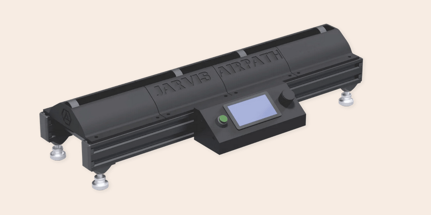
Build your own filament cooling system
Published 3y. Edited 1yPublished about 3 years ago. Last edit over 1 year ago
In this how to we will show you how you can assemble your JARVIS Airpath cooling system in 6 easy steps
In tis folder you will find:
1. Airpath parts.(pdf)
2. Airpath 3D printed parts.(zip)
You can check out our JARVIS Airpath video here:
https://youtu.be/6Ae6oDKhqiE
Feel free to visit our website :)
https://www.qitech.de/en/industriesMachines
productextrusionmelting
%20--%3e%3csvg%20version='1.1'%20id='Calque_1'%20xmlns='http://www.w3.org/2000/svg'%20xmlns:xlink='http://www.w3.org/1999/xlink'%20x='0px'%20y='0px'%20viewBox='0%200%2027.2%2027.8'%20style='enable-background:new%200%200%2027.2%2027.8;'%20xml:space='preserve'%3e%3ctitle%3eicon%20redirect%20new%3c/title%3e%3cg%3e%3cpath%20d='M27.2,26.5c-0.1-5-0.3-10-0.4-15c0-0.7-0.6-1.2-1.2-1.2s-1.2,0.6-1.2,1.2c0.1,4.6,0.3,9.1,0.4,13.7%20c-3.9-0.2-7.7-0.6-11.6-0.4c-3.3,0.2-6.7,0.5-10,0.4C2.8,19.5,2.7,13.7,2.5,8c2.9-0.1,5.8-0.8,8.6-0.7c1.6,0.1,1.6-2.4,0-2.5%20C7.8,4.6,4.5,5.7,1.2,5.5c-0.6,0-1,0.3-1.1,0.7C0,6.3,0,6.4,0,6.6c0,0,0,0.1,0,0.1c0,0,0,0,0,0.1c0.2,6.6,0.4,13.2,0.5,19.7%20c0,0.6,0.4,1.3,1.2,1.4c3.8,0.1,7.5-0.2,11.3-0.4c4.4-0.3,8.6,0.2,12.9,0.4c0.6,0,1-0.3,1.1-0.7C27.1,26.9,27.2,26.7,27.2,26.5z'/%3e%3cpath%20d='M12,12.6c-0.2,0.7,0.2,1.4,0.9,1.5c0.7,0.2,1.4-0.2,1.5-0.9v0c0.6-2.2,1.4-4.5,3.1-6c1.3-1.2,3-1.9,4.7-2.7%20c-0.4,1.3-0.8,2.6-1.4,3.8c-0.6,1.5,1.8,2.1,2.4,0.7c0.8-1.9,1.5-3.9,2-5.9c0-0.1,0-0.2,0-0.3c0.3-0.6,0.1-1.5-0.7-1.8%20C22.3,0.4,20,0,17.7,0c-0.7,0-1.2,0.6-1.2,1.2s0.6,1.2,1.2,1.2c0.9,0,1.7,0.1,2.6,0.2c-1.7,0.8-3.4,1.7-4.8,3%20C13.6,7.6,12.7,10.1,12,12.6z'/%3e%3c/g%3e%3c/svg%3e)
More Information

%20--%3e%3csvg%20version='1.1'%20id='Layer_1'%20xmlns='http://www.w3.org/2000/svg'%20xmlns:xlink='http://www.w3.org/1999/xlink'%20x='0px'%20y='0px'%20viewBox='0%200%2064%2063'%20style='enable-background:new%200%200%2064%2063;'%20xml:space='preserve'%3e%3cstyle%20type='text/css'%3e%20.st0{fill:%23231F20;}%20%3c/style%3e%3cdesc%3eCreated%20with%20Sketch.%3c/desc%3e%3cg%20id='Page-1'%3e%3cg%20id='OA-Logo-Black-Background'%3e%3cpath%20id='Shape'%20class='st0'%20d='M14.1,30.1c-1.5-0.8-8.6-3.8-14.1-7.8c1.8-3.4,3.1-5.6,5-9.1c2.7,1.1,1.9,0.5,4.6,1.7%20c0.8,0.4,10.1,4.5,13.8,6.2c2.4,1.1,4.7,2.2,7,3.3L43,30.5l8.1,3.9c4,2,7.2,3.5,11.3,5.5c0.5,0.3-3.7,9.4-3.7,9.4%20c-1.7-0.6-3.9-1.8-5.5-2.5c-4.7-2.1-9-3.9-13.7-6c-4-1.8-6.7-2.9-10.8-4.5C25,34.9,17.1,31.6,14.1,30.1z'/%3e%3cpath%20id='Shape_1_'%20class='st0'%20d='M12.1,54.9c-0.8,0.6-1.6,1.2-2.5,1.6c-0.4-0.5-0.9-1-1.3-1.5c-0.3-1.2-2.3-4.9-2.7-6.2%20c-0.1-0.4-0.7-2.2-0.8-2.6c0,0,5-3.4,8.2-5.9c3.2-2.6,6.2-5,9.3-7.5c1.4-1.1,3.9-2.5,5.3-3.5c2.5-1.7,13-9.1,15.6-10.5%20c5.4-3.3,11.1-6.3,16.8-9c1.7,3.5,1.8,3,3.8,6.9c0,0-17.8,13.5-22.7,17.1c-3.8,2.8-7.5,5.7-11.3,8.5c-1.7,1.3-3.5,2.4-5.2,3.7'/%3e%3cpath%20id='Shape_2_'%20class='st0'%20d='M20.8,2.9l-0.2-0.8C25,0,31.2-0.3,31.4,0.2c0.4,1.1,0.9,2.2,1.2,3.4c1.4,4.4,2.7,8.7,4,13.1%20c0.4,1.4,2.8,10,2.9,10.5c0.5,2.8,1.2,5.6,1.6,8.4c0.8,4.7,1.4,8.6,2.3,13.3c0.6,3.1,1.3,6.3,2.3,11.3c0,0-5.8,1.4-7.5,1.8%20c-0.8,0.2-1.5,0.4-2.4,0.6c-0.3-1.1-0.2-1.2-0.5-2.1c-0.9-3.7-1.8-7.3-2.6-11c-1.5-6.4-3-12.9-4.4-19.3%20c-1.2-5.4-2.6-10.7-4.4-15.9c-1-3.1-1.8-6.3-2.7-9.5C21.1,3.8,21,3.8,20.8,2.9z'/%3e%3c/g%3e%3c/g%3e%3c/svg%3e)


1
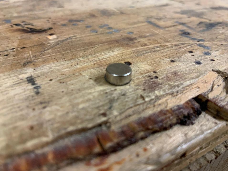
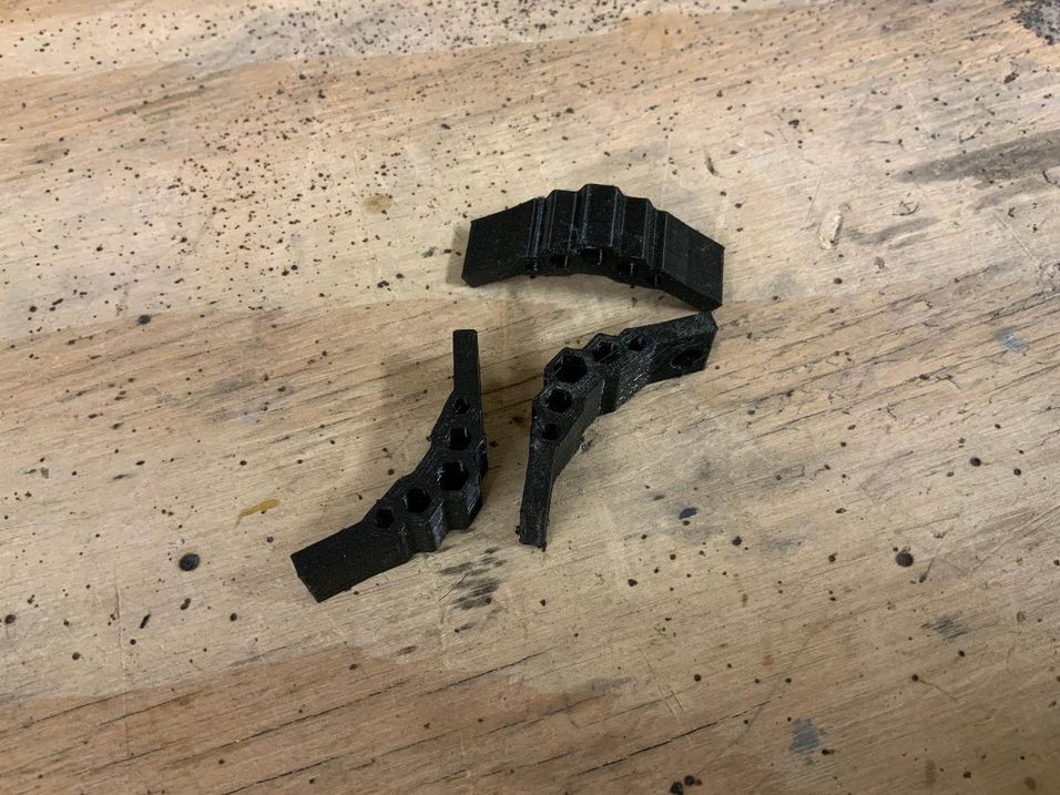
Preparation of the gondolas
First, prepare the 4 gondolas by pressing the included magnets into the upper holes. Later, the clips, which also carry magnets, will be attached to them. Make sure that all the magnets in the gondolas are oriented in the same polarity so that the magnet clips will be attracted to them later from the opposite polarity.
The clips have 2 holes on the inside for the magnets. Insert the magnets in the correct orientation so that the magnet clips are attracted to the gondolas.
2
Attachment of the gondolas to the aluminum profile
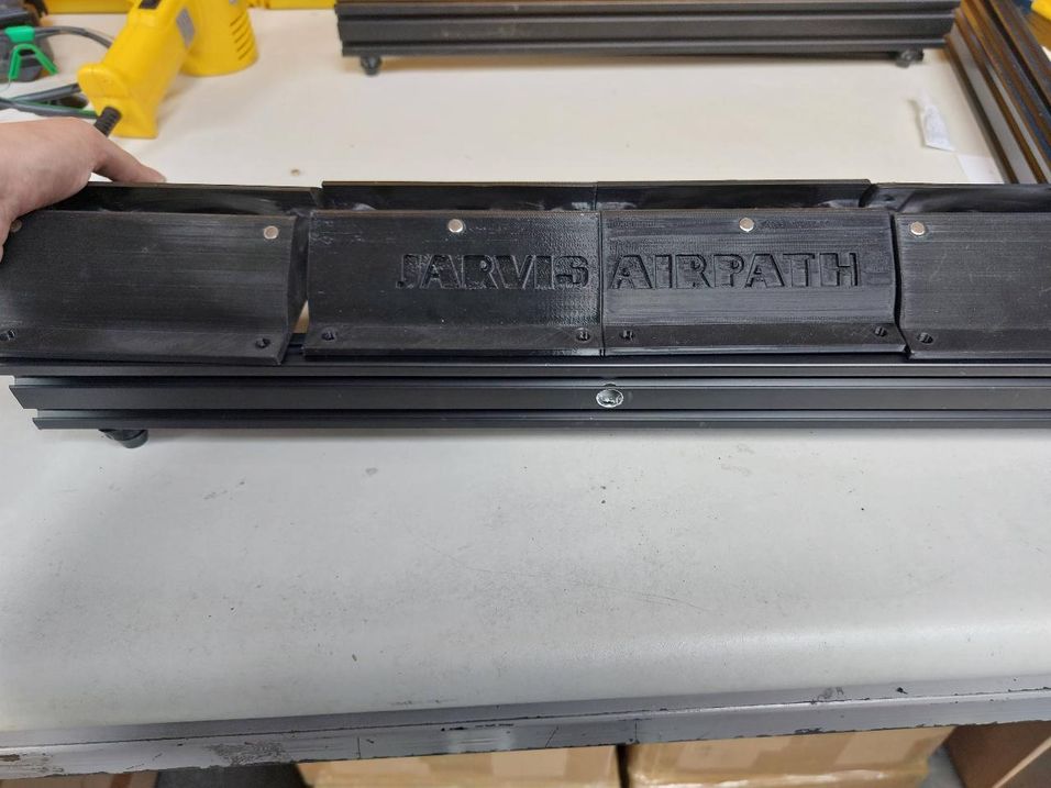
Next, we will attach the 4 gondolas to the aluminum profiles. For this, you will need 16 T-nuts, 16 screws of size M5 x 8, both aluminum profiles, the 4 gondolas, and an Allen key of size 3.
Make sure that the front side is the one where the labeling and display are visible and accessible. On the aluminum profiles, there is a hole for the front side.
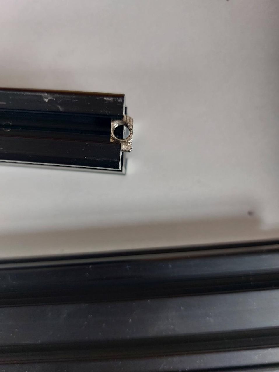
Slide the T-nuts into the aluminum profile. The rounded side should face downwards, while the flat side should face upwards. Attach the gondolas to the aluminum profiles using the screws. Pay attention to the order as shown in the illustration. The outer gondolas have a logo that faces outward, while the inner ones have labeling. Ensure that the gondolas do not extend beyond the aluminum profiles. The aluminum profiles should protrude about 2 mm outward.
3
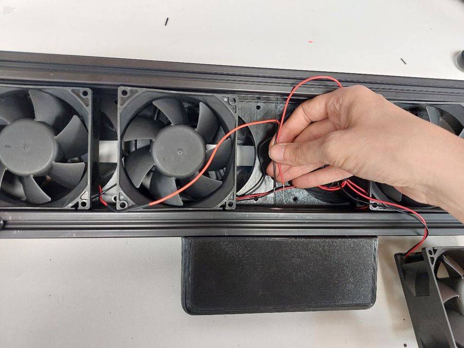
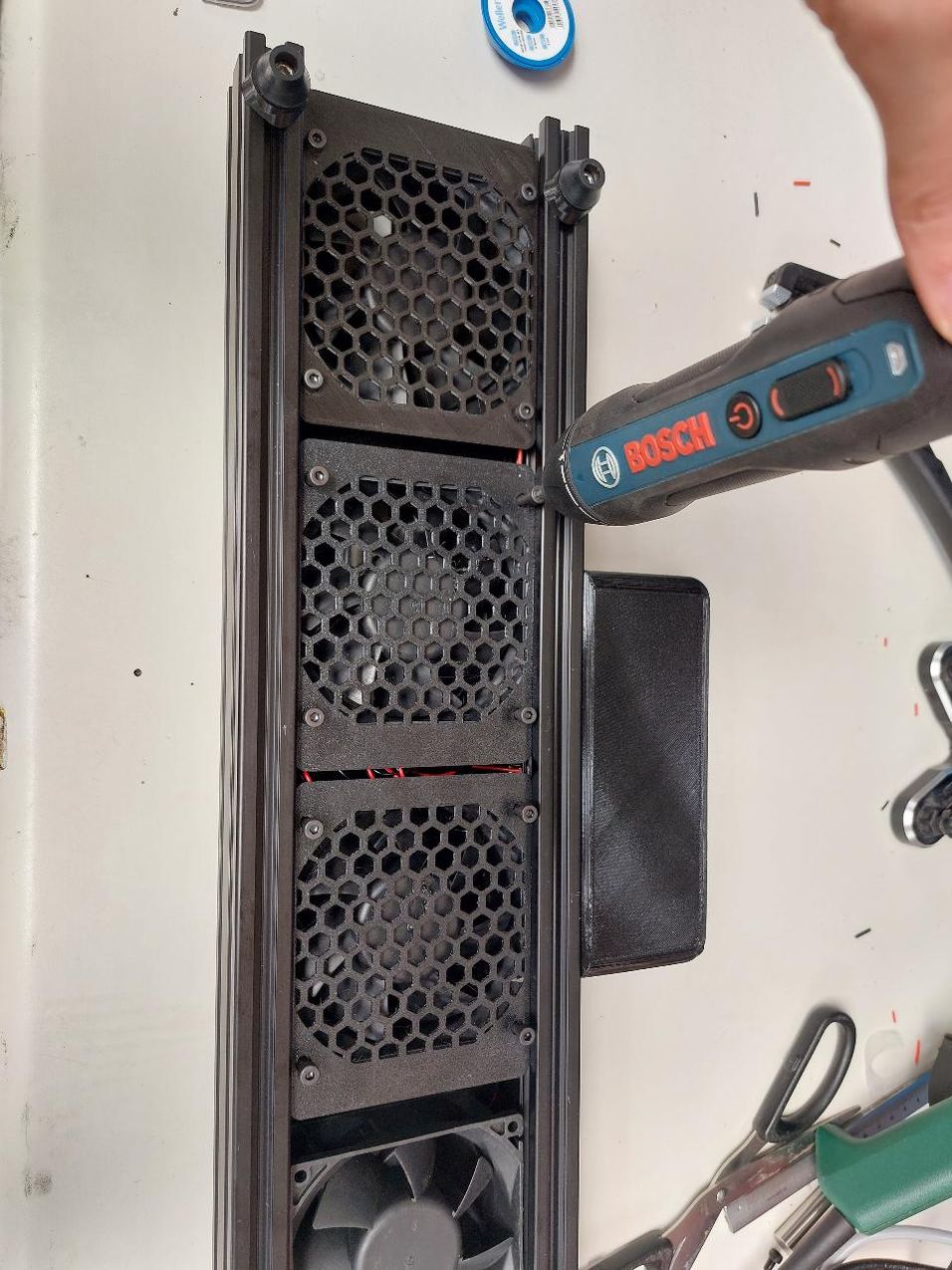
Insertion of fans
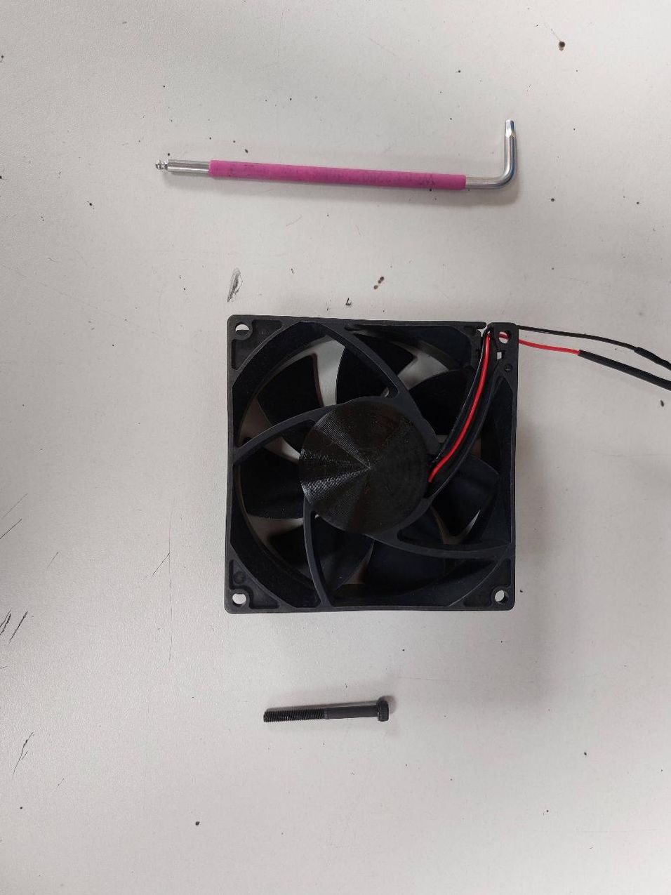
Now you can flip the JARVIS Airpath over, as you need to screw in the fans here. Insert the fans into the system, making sure that the tips of the cones are facing inward and the cables for the display are pulled out through the hole in the aluminum profile. Ensure that the fans rotate without touching the cables. Screw the grilles and fans onto the gondola.
4
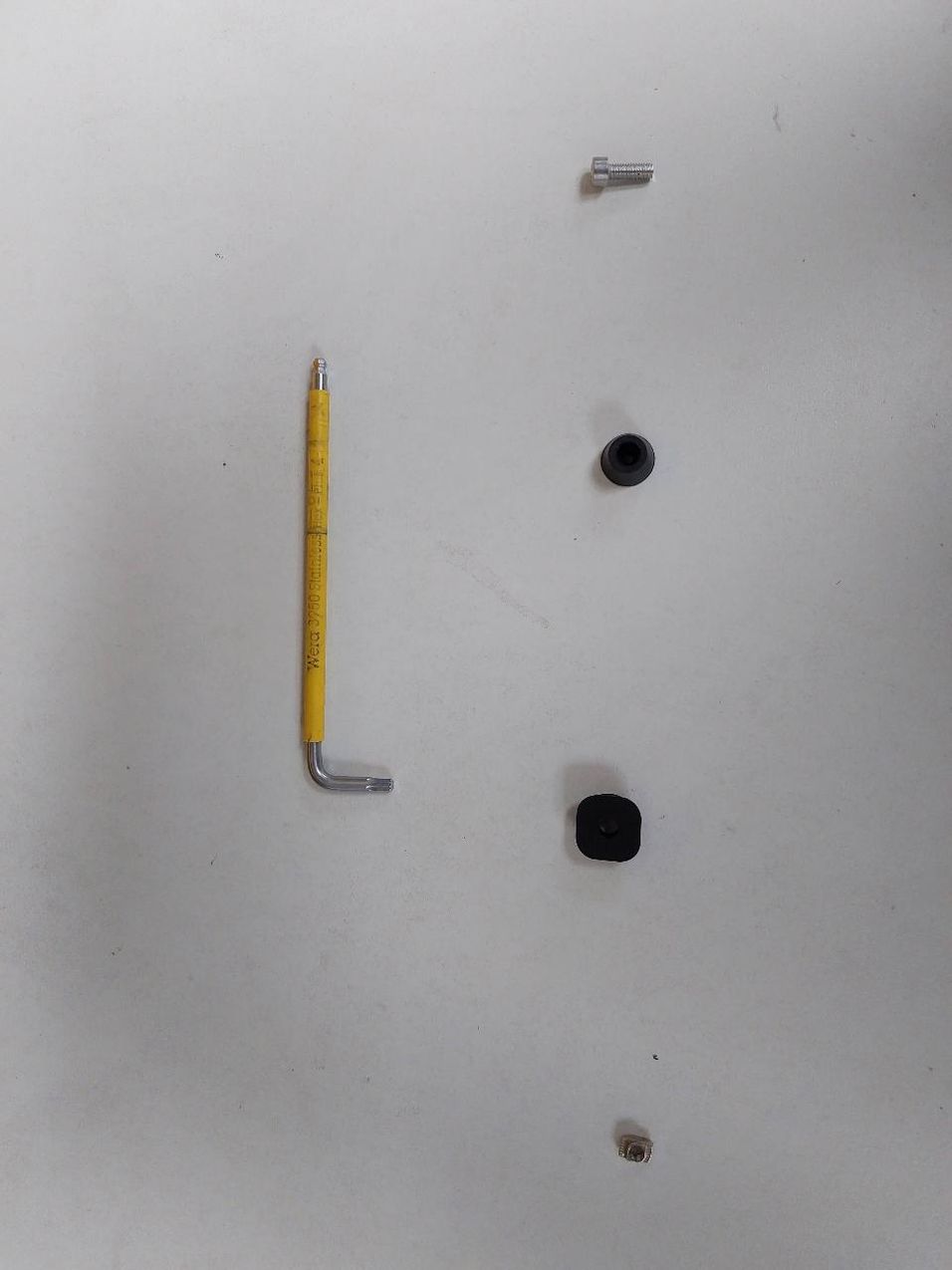
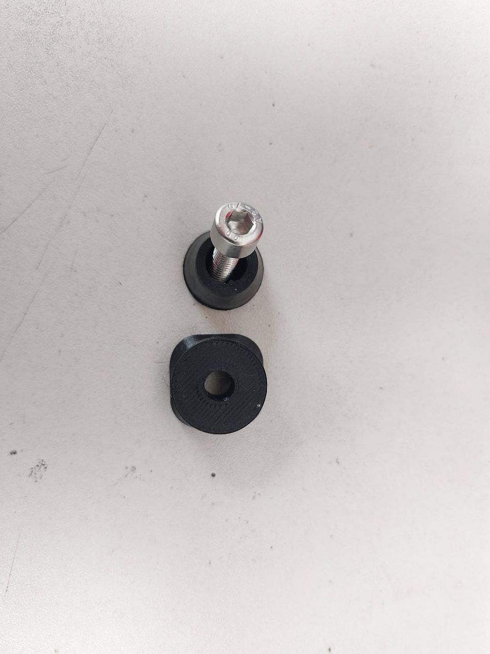
Attaching the support feet
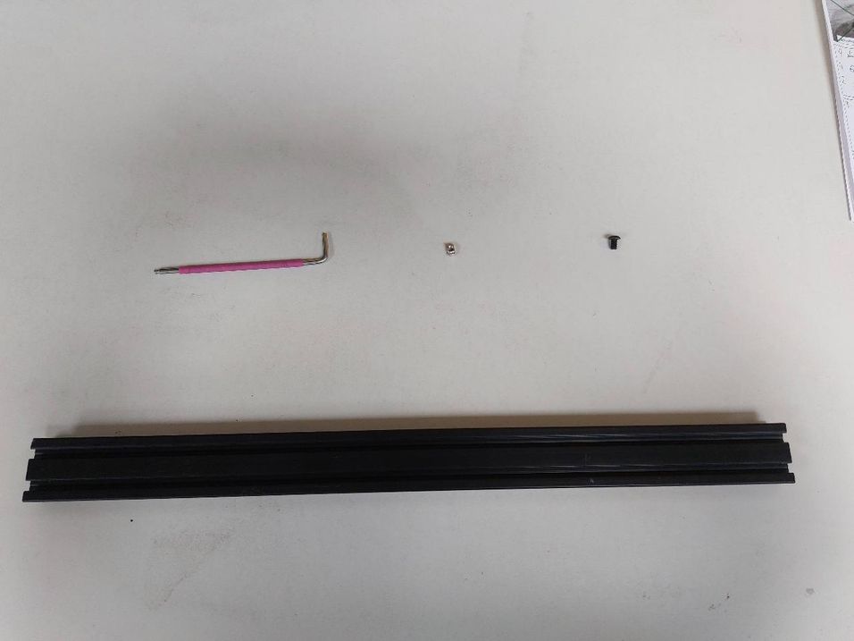
To screw the feet securely, you will need 4 T-nuts, 4 hard plastic washers, 4 rubber feet, 4 screws in size M5 x 14, and an Allen key in size 4.
The JARVIS Airpath is placed on the rubber feet. The hard plastic washers are positioned between the rubber feet and the aluminum profile. Screw two support feet into the aluminum profile.
5
Attaching the control box
Now you will attach the control box. For this, you will need 4 T-nuts and 4 screws in size M5 x 8.
Insert the T-nuts into the aluminum profile and screw the control box onto the front side. Make sure to route the power cables through the hole into the box.
-188ba3ce499.jpg?width=956&resize=contain)
-188ba3dad97.jpg?width=956&resize=contain)
-188ba3e58b4.jpg?width=956&resize=contain)
6
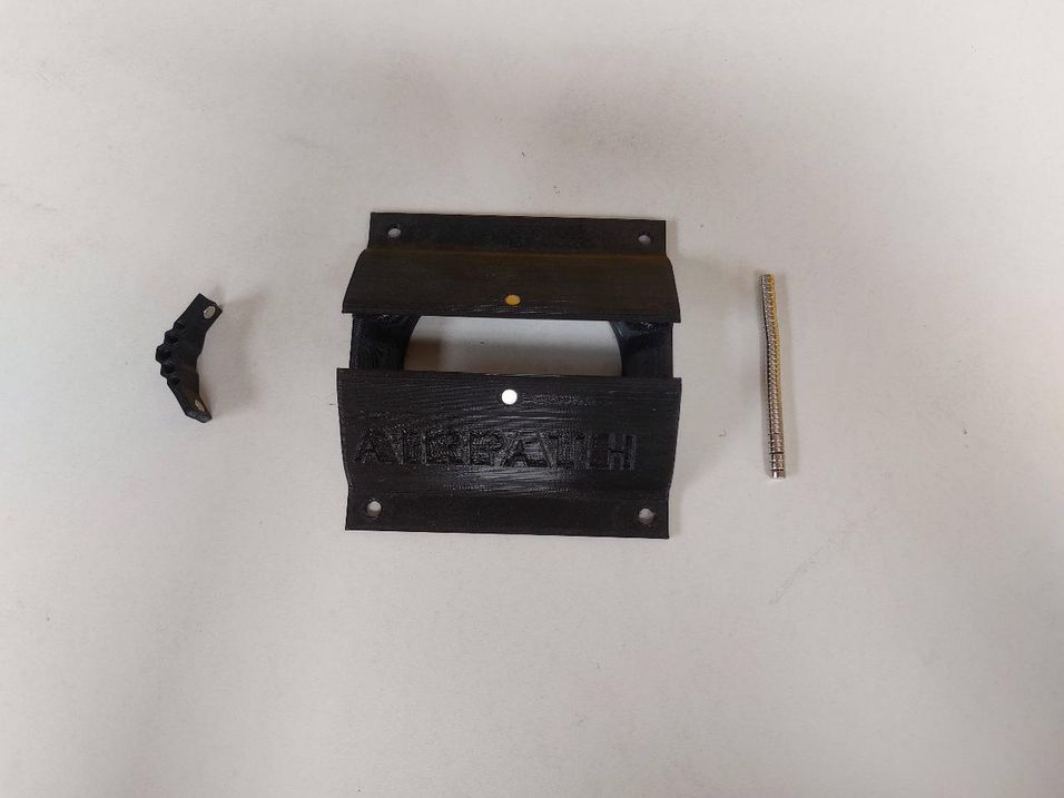
Completion of the control box
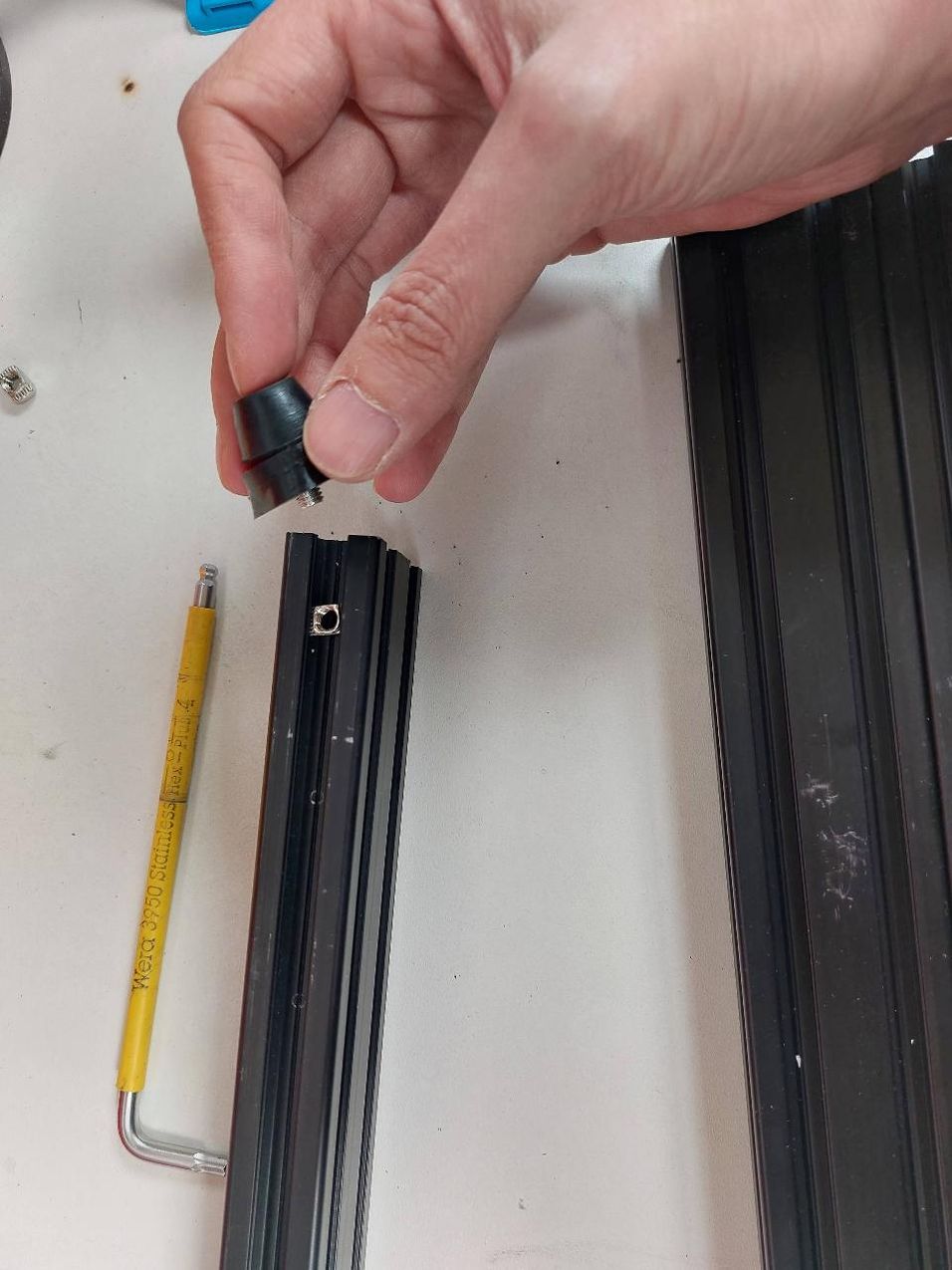
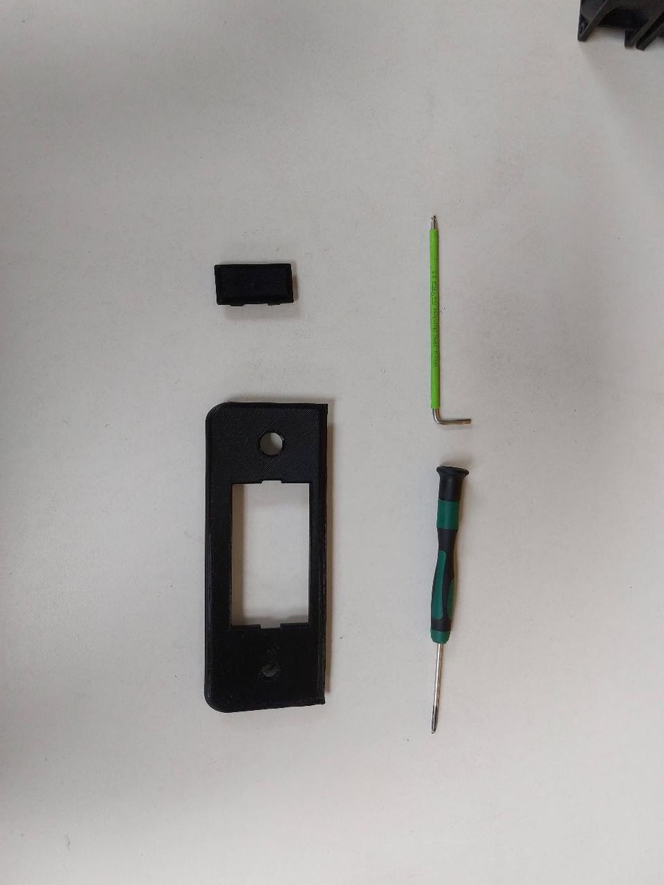
You now need the control cover, the display box, the DC jack, 4 set screws, an Allen wrench size 2.5, and a small screwdriver size 0.35 / 2.5.
Open the display box and remove the green start button from the palette.
Now, attach the display to the control cover. The black border on the display should face downward. Insert the fan control through the smaller hole. Insert the green start button through the larger hole and place it back into the palette. On the inside, first secure the buttons with the thin metal ring, and then tighten the nut.
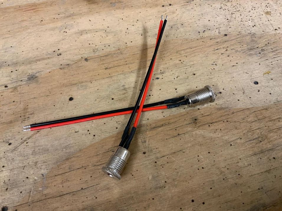
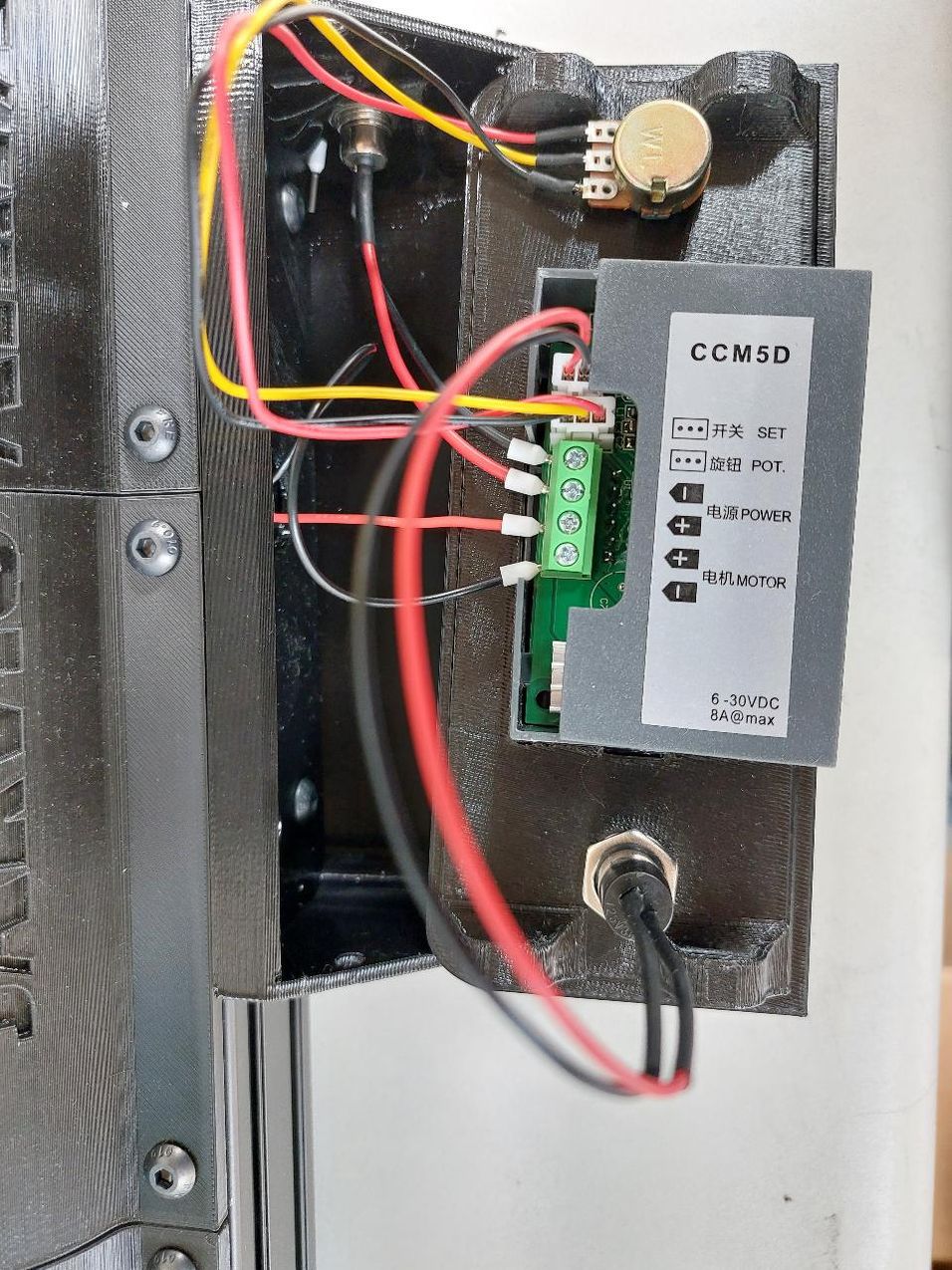
Attach the DC jack through the side hole of the control box. Thread the cables through the hole into the box.
Before closing the box, screw the cables into the designated terminals. The black cables go into the "-" symbol, and the red cables go into the "+" marking.
Secure the control box to the display cover using the set screws.
%20--%3e%3csvg%20version='1.1'%20id='Layer_1'%20xmlns='http://www.w3.org/2000/svg'%20xmlns:xlink='http://www.w3.org/1999/xlink'%20x='0px'%20y='0px'%20viewBox='0%200%2064%2063'%20style='enable-background:new%200%200%2064%2063;'%20xml:space='preserve'%3e%3cstyle%20type='text/css'%3e%20.st0{fill:%2320B7EB;}%20.st1{fill:%23E9475A;}%20.st2{fill:%23FECE4E;}%20%3c/style%3e%3cdesc%3eCreated%20with%20Sketch.%3c/desc%3e%3cg%20id='Page-1'%3e%3cg%20id='OA-Logo-Black-Background'%3e%3cpath%20id='Shape'%20class='st0'%20d='M14.1,30.1c-1.5-0.8-8.6-3.8-14.1-7.8c1.8-3.4,3.1-5.6,5-9.1c2.7,1.1,1.9,0.5,4.6,1.7%20c0.8,0.4,10.1,4.5,13.8,6.2c2.4,1.1,4.7,2.2,7,3.3L43,30.5l8.1,3.9c4,2,7.2,3.5,11.3,5.5c0.5,0.3-3.7,9.4-3.7,9.4%20c-1.7-0.6-3.9-1.8-5.5-2.5c-4.7-2.1-9-3.9-13.7-6c-4-1.8-6.7-2.9-10.8-4.5C25,34.9,17.1,31.6,14.1,30.1z'/%3e%3cpath%20id='Shape_1_'%20class='st1'%20d='M12.1,54.9c-0.8,0.6-1.6,1.2-2.5,1.6c-0.4-0.5-0.9-1-1.3-1.5c-0.3-1.2-2.3-4.9-2.7-6.2%20c-0.1-0.4-0.7-2.2-0.8-2.6c0,0,5-3.4,8.2-5.9c3.2-2.6,6.2-5,9.3-7.5c1.4-1.1,3.9-2.5,5.3-3.5c2.5-1.7,13-9.1,15.6-10.5%20c5.4-3.3,11.1-6.3,16.8-9c1.7,3.5,1.8,3,3.8,6.9c0,0-17.8,13.5-22.7,17.1c-3.8,2.8-7.5,5.7-11.3,8.5c-1.7,1.3-3.5,2.4-5.2,3.7'/%3e%3cpath%20id='Shape_2_'%20class='st2'%20d='M20.8,2.9l-0.2-0.8C25,0,31.2-0.3,31.4,0.2c0.4,1.1,0.9,2.2,1.2,3.4c1.4,4.4,2.7,8.7,4,13.1%20c0.4,1.4,2.8,10,2.9,10.5c0.5,2.8,1.2,5.6,1.6,8.4c0.8,4.7,1.4,8.6,2.3,13.3c0.6,3.1,1.3,6.3,2.3,11.3c0,0-5.8,1.4-7.5,1.8%20c-0.8,0.2-1.5,0.4-2.4,0.6c-0.3-1.1-0.2-1.2-0.5-2.1c-0.9-3.7-1.8-7.3-2.6-11c-1.5-6.4-3-12.9-4.4-19.3%20c-1.2-5.4-2.6-10.7-4.4-15.9c-1-3.1-1.8-6.3-2.7-9.5C21.1,3.8,21,3.8,20.8,2.9z'/%3e%3c/g%3e%3c/g%3e%3c/svg%3e)